The Exchange 2007 unified
messaging features and telephony integration bring a whole new set of
concepts, terminology, and architectural elements to the Exchange
platform. This section explores these different components, objects,
protocols, and services.
Unified Messaging Components
The central repository for
all the unified messaging components is Active Directory. The schema
extensions that are installed as part of the Exchange 2007 prerequisites
add a variety of objects and attributes that support the UM
functionality. These objects are as follows:
The objects and their relationships are illustrated in the example shown in Figure 1.
The example consists of two locations, San Francisco (SFO) and Paris
(PAR), with an integrated Exchange 2007 unified messaging
infrastructure. The unified messaging objects are shown with a dotted
line around them to separate them from the telephony objects.
When a UM hunt group is
created manually, not only does the associated UM IP gateway and the
associated UM dial plan get specified, but also a pilot identifier is
specified.
This diagram is referenced in the subsequent sections describing the various unified messaging objects and components.
Dial Plan Objects
Dial
plans are the central component of the Exchange 2007 unified messaging
architecture. A UM dial plan essentially logically corresponds to PBX or
subsets of extensions within a PBX. The UM dial plan objects can be
found in the Exchange Management Console on the UM Dial Plan tab of the
Organization, Unified Messaging container.
Different PBXs with an organization, such as between SFO and PAR in Figure 24.6,
can have overlapping extensions. For example, a user in San Francisco
might have extension 150 and a user in Paris might also have extension
150. Because the two users are on different PBXs, there is no inherent
conflict. However, when Exchange 2007 Unified Messaging is deployed and
the telephony infrastructure is unified in Active Directory, then there
would be a conflict.
Dial plans ensure that
all extensions are unique within the architecture by mapping a dial plan
to a PBX. Extensions within a dial plan must be unique. However,
extensions between
different dial plans do not have to be unique. A user can only belong
to a single dial plan and will have an extension number that uniquely
identifies him within the dial plan.
In the figure, there is one
dial plan for each location. In the example, San Francisco is the large
office with more users and Paris is smaller. There could be multiple
dial plans per location.
Dial plans also provide a way to set up common settings among a set of users, such as the following :
Number of digits in an extension
Ability to receive faxes
Subscriber greetings
Whom caller can contact within the dial plan
Call durations
Users call restrictions (international calls)
Languages supported
Note
When a new UM dial plan object is created, a default UM mailbox policy object is also created and associated with the dial plan.
The dial plan also associates the extension for the subscriber access to Outlook Voice Access.
There can be multiple dial plans within an architecture and even associated with the same PBX.
UM IP Gateway Objects
The UM IP
gateway object is the logical representation of the physical IP/VoIP
gateway. The UM IP gateway object is a critical component, in that it
specifies the connection between the UM dial plan and the physical
IP/VoIP gateway. The major configuration of the UM IP gateway object is
the IP address of the IP/VoIP gateway device it represents and the
associated dial plan. The UM IP gateway objects can be found in the
Exchange Management Console on the UM IP Gateway tab of the
Organization, Unified Messaging container.
The UM IP gateway is
created as enabled. The gateway can be disabled, either immediately
(which disconnects any current calls) or specifying to disable after
completing calls. The latter mode disables the gateway for any new calls but does not disconnect any current calls.
If a UM IP gateway
object is not created or is deleted, the Unified Messaging servers in
the dial plan will not be able to accept or process calls.
Within the same Active
Directory, there can only be one UM IP gateway object for each physical
IP/VoIP gateway, and it is enforced through the IP addresses.
UM IP gateway objects can
be associated with multiple dial plans. This is accomplished by creating
multiple hunt groups, as discussed in the following section.
Hunt Group Objects
In the telephony world,
hunt groups are collections of lines that a PBX uses to organize
extensions. The hunt group collections allow the system to treat the
extensions as a logical group. Hunt groups are used for incoming lines,
for outgoing lines, and to route calls to groups of users such as the
Sales department. The UM hunt group objects can be found in the Exchange
Management Console on the UM IP Gateway tab of the Organization,
Unified Messaging container. They are listed under each of the UM IP
gateways.
Calls with a hunt group can be routed using different methods or algorithms, such as the following:
Rollover— The PBX starts with the lowest numbered line each time and increments until it finds a free line.
Round-robin—
The PBX rotates equally among all the lines when starting and then
rolls over from that starting point. This ensures that the calls are
distributed evenly within the hunt group.
Utilization—
The PBX tracks extension utilization and routes the call to the least
utilized line first, and then rolls over to the next least busy line.
These algorithms basically encode what the organization deems the appropriate behavior for the routing.
Each hunt group has an
associate pilot number, which is the extension that is dialed to access
the hunt group. This is frequently the lowest numbered extension in the
set of extensions because the most common implementation of a hunt group
is rollover.
Within Exchange 2007, the
UM hunt group object performs a different function. Essentially, the UM
hunt group object maps the IP/VoIP gateway and an extension to a UM dial
plan.
Note
If
a default hunt group is created when the UM IP gateway object is
created, that UM hunt group will not have a pilot extension associated
with it. This creates call routing problems if you create additional
hunt groups, so it is best to remove the default hunt group. When a new
UM hunt group is created after that, the pilot identifier must be
specified.
Additional UM hunt groups can be created to route different incoming extensions to different UM dial plans.
There is no limit to the
number of UM hunt group objects that can be created. There must be at
least one hunt group per UM IP gateway object for calls to be routed to a
dial plan.
Mailbox Policy Objects
Mailbox policy
objects control unified messaging settings and security for users. The
UM mailbox policy objects can be found in the Exchange Management
Console on the UM Mailbox Policies tab of the Organization, Unified
Messaging container.
These settings include the following:
Mailbox policies are created to control security and provide customized messages to users. For example, in Figure 24.6
the SFO Mailbox Policy 1 is a general user policy with default PIN
settings that require a minimum of 6 characters. The second policy, SFO
Mailbox Policy 2, is for executives with higher security requirements
and more secure PIN settings that require a minimum of 10 characters.
The UM mailbox policy is
associated with one and only one UM dial plan, but dial plans can be
associated with multiple mailbox policies. This allows the dial plan to
be associated to the users associated with the mailbox policy. Each user
will be associated with one and only one UM mailbox policy object, but
many users can be associated with a single mailbox policy object.
There is no limit to the number of UM mailbox policy objects that can be created.
Auto Attendant Objects
The auto attendant
provides an automated phone answering function, essentially replicating a
human secretary. The auto attendant answers the incoming calls,
provides helpful prompts, and directs the caller to the appropriate
services. The UM auto attendant objects can be found in the Exchange
Management Console on the UM Auto Attendant tab of the Organization,
Unified Messaging container.
The auto attendant
supports both phone key press (DTMF) and voice commands. This
sophisticated voice recognition technology allows the caller to navigate
the menus and prompts with nothing more than their voice if they want
to.
The auto attendant objects support the following configurable features:
Customized greetings and menus for business hours and nonbusiness hours
Predefined and custom schedule to specify business hours and time zone
Holiday schedule for exceptions to the business hour schedule
Operator extension and allowing transfer to operator during business and nonbusiness hours
Key
mapping to enable the transfer of callers to specific extensions or
other auto attendants based on hard-coded key presses or voice commands.
Note
Everyone has felt
the frustration of moving through an automated call system and not being
able to reach an operator or a live person. With Unified Messaging, the
Exchange administrator now has control over that behavior.
The auto attendant can
allow or disallow transfer to the operator by specifically allowing or
disallowing transfer to the operator during business and nonbusiness
hours.
The author’s recommendation is to allow transfers to the operator at least during business hours to reduce caller frustration.
Each auto attendant can
be mapped to specific extensions to provide a customized set of prompts.
For example, an organization could set up one auto attendant to support
the sales organization calls with specific prompts for handling calls
to sales. The organization could then set up a second auto attendant to
support the service organization with specific prompts for technical
support and help. These would service different pilot numbers, depending
on the number that the caller used.
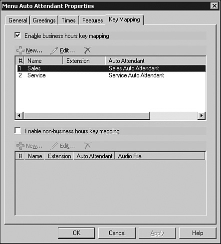
A front-end menu can
be created with key mapping and an auto attendant with customized
prompts. This allows the organization in the previous example to create a
top-level auto attendant that would prompt callers to “Press or say 1
for Sales or 2 for Service” and then perform the appropriate transfer. Figure 2 shows the key mapping configuration, which would be accompanied by customized prompts.
There
is no limit to the number of auto attendants that can be created in
Active Directory. An auto attendant can only be associated with a single
dial plan, though a dial plan can be associated with multiple auto
attendants.
