In a solution package, the
FeatureManifest element is used to specify the reference to the manifest
file for a particular feature. To a certain extent, features work in a
similar way to solutions in that they can contain a number of individual
components and make use of a manifest file to specify what should be
done with these components.
Feature Designer
Using
the Example19 project that we created earlier, double-click the
Feature1 node in the Features folder to display the Feature Designer:
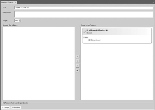
As you know, features are individual items of
functionality that can be activated or deactivated within a SharePoint
farm. You can see in the Feature Designer that features comprise one or
more elements, where an element may be a web part, a list definition, a
workflow, or a number of different components. Using the Feature
Designer, we can select which elements should be included in a feature
and therefore specify which functionality will be enabled when the
feature is activated.
Activation Dependencies
For the most part, we don’t need to think about
feature elements, because Visual Studio automatically creates features
for us and adds our project items to them. However, in the real world,
this default behavior may not be appropriate. For example, rather than
having many features, each with a different project item in it, we may
want to consolidate related items into a single feature. This makes it
easier for users to activate our customization since they need to
activate only one feature rather than many separate items. It also makes
it easier for us to ensure that all the parts of our solution are
activated.
We
can consolidate related items in a few ways: We can use the Feature
Designer to specify which elements should be included in a feature, or
we can define feature dependencies. Where a dependency is defined, a
feature cannot be activated unless its dependencies have also been
activated. This may seem like a poor solution, because it means that
users still have to activate a load of individual features, but we can
take this a step further. Under some circumstances, dependency features
will be automatically activated when a feature that depends upon them is
activated. Furthermore, we can hide features so that they don’t appear
in the feature activation user interface. Effectively, this brings us
back to the idea of a single activation click for our customization,
while at the same time allows us to keep individual features relatively
simple.
Feature Scope
The activation dependency approach has a few
limitations, but before we look at those, we need to consider feature
scope. Again, this is something that we’ve been able to ignore because
Visual Studio handles it for us automatically; in the real world, an
understanding of scope is essential when building complex solutions.
In the Feature Designer, under the Description text
box is a drop-down that we can use to select the scope of a feature:
Farm, WebApplication, Site, and Web. As you’ve probably guessed, these
options determine the level at which the components are activated.
Components within a feature scoped as Web will be activated for a single
site only, whereas components within a feature scoped as Farm will be
available to the entire farm. However, it’s not quite as straightforward
as that. Not all types of component can be installed in all scopes. For
example, if we’re creating a content type, we can deploy it only using a
feature scoped at the Site level; if we’re adding an event receiver, it
can be scoped only at the Web level. You can find a complete list of
what goes where at http://msdn.microsoft.com/en-us/library/ms454835.aspx.
Feature Activation Rules
To return to our discussion of the limitations of
feature dependencies, the first limitation concerns scope. Features
cannot be dependent on features of a more restrictive scope—that is, a
feature scoped at the site collection (Site) level cannot depend on a
feature scoped at the site (Web) level. This makes sense when you think
about it, because a site collection can contain multiple sites, each
with its own set of activated features—so there’s no way to satisfy such
a dependency properly. The opposite is not true, however. Features
scoped at the site level can depend on features at the site collection
level. There is one caveat to this rule: A feature can’t depend on
another feature at a higher scope if the higher level feature is not
visible. So a site feature can’t be dependent on a site collection
feature that’s hidden. There is a good reason for this: Although we can
automatically activate dependent features, we can do so only within the
same level. So we would be unable to activate our site feature because
there would be no way to activate the site collection feature upon which
it depended if the site collection feature were hidden.
The second limitation concerns dependency chains.
Generally speaking, activations can be only one level deep. For example,
if feature A depends on feature B, then feature B cannot have any
dependencies. This is true only for visible dependencies, however. If
feature B is dependent
upon feature C, which is hidden, then the dependency chain is allowed.
Hidden features cannot have any dependencies; therefore, the maximum
chain depth is two levels.
Feature Properties
With the Feature Designer open, we can set feature
properties using the Properties pane in Visual Studio. For example, we
can hide a feature by setting the Is Hidden property to True. Many of
the properties are set automatically by Visual Studio, but the following
properties can also be used to meet specific configuration
requirements:
Activate on Default This Boolean value dictates whether the feature should be activated when the solution package is deployed.
Always Force Install
The SharePoint deployment mechanism is pretty clever when it comes to
installing features. Because features can be shared by many solutions,
only features that are not already installed are installed when a
package is deployed. Each feature has a unique identifier that’s used as
the reference for activation dependencies and so on. To force an
installation when the solution is deployed, this value can be set to
True.
Deployment Path All features are deployed to their own folder at %SPROOT%TEMPLATE\FEATURES\. By default, Visual Studio creates folders named ProjectName_FeatureName.
In our project, our feature will be deployed in a folder named Example19_Feature1. We can change the name of this folder by changing
the Deployment Path. (The name Deployment Path is something of a
misnomer; it more accurately contains the Deployment folder name.)
Image URL & Image Alt Text
In the Manage Features page, an icon appears to the left of each
feature’s description. These properties can be used to specify an
alternative image file and appropriate alternative text if required. In
no alternative is specified, the default feature icon will be used.
We’ll look at few other properties, such as Receiver
Assembly, Upgrade Actions Receiver Assembly, and Version in more detail
in later sections.
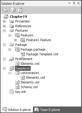
Feature Elements
With a few exceptions, almost all the items we can
add to a project using Visual Studio are packaged as feature elements.
In our demonstration project, we added an empty element named
FirstElement; in the Solution Explorer page, we can see that it contains
a single file named Elements.xml. In the Feature Designer, we can click
the Manifest button at the bottom of the page to see the manifest file
for the feature:
<Feature xmlns="http://schemas.microsoft.com/sharepoint/"
        Title="Example19 Feature1" Id="5fcd733e-2cc9-4363-85fd-dfe7893cb195"
        Scope="Web">
  <ElementManifests>
    <ElementManifest Location="FirstElement\Elements.xml" />
  </ElementManifests>
</Feature>
Similar
to how the manifest file for the solution was made up of
FeatureManifest elements, we can see that the feature manifest is made
up of ElementManifest elements.
Let’s add a more complex element to our project to see how this is represented:
In Visual Studio, choose Project | Add New Item. In the Add New Item dialog, select List Definition and name the element SampleList.
In
the SharePoint Customization Wizard dialog, accept the defaults and
then click Finish. A new SampleList folder will be added to the project,
as shown:
If we look at the feature manifest file again, we can see that three new elements have been added:
<Feature xmlns="http://schemas.microsoft.com/sharepoint/"
       Title="Example19 Feature1" Id="5fcd733e-2cc9-4363-85fd-dfe7893cb195"
       Scope="Web">
  <ElementManifests>
    <ElementManifest Location="FirstElement\Elements.xml" />
    <ElementManifest Location="ListInstance1\Elements.xml" />
    <ElementManifest Location="SampleList\Elements.xml" />
    <ElementFile Location="SampleList\Schema.xml" />
  </ElementManifests>
</Feature>
Two new ElementManifest elements point to the new
Elements.xml files that were added and an ElementFile element. This
prompts the question, What’s the difference between an ElementManifest
and an ElementFile? We’ll find the answer by examining the Elements.xml
file in the SampleList folder:
<Elements xmlns="http://schemas.microsoft.com/sharepoint/">
    <ListTemplate
        Name="SampleList"
        Type="10000"
        BaseType="0"
        OnQuickLaunch="TRUE"
        SecurityBits="11"
        Sequence="320"
        DisplayName="Example19 - SampleList"
        Description="My List Definition"
        Image="/_layouts/images/itann.png"/>
</Elements>
In
our Elements file, we’re specifying that we are creating a new
ListTemplate. Our Elements file is effectively issuing a command to the
deployment framework. If we open the Schema.xml file, we find much more
information contained within it. The Schema file is effectively a
resource file that’s used by the deployment framework to provision our
list template. Another way to look at it is that our ElementManifest
files dictate what should be done, whereas our ElementFile files provide
the required resources to do the job.
A number of commands can be issued using
ElementManifest files, and although these are mostly wrapped by a
SharePoint Project Item in Visual Studio, a complete list can be found
at http://msdn.microsoft.com/en-us/library/ms414322.aspx.
To get a better understanding
of the significance of this, we can navigate to
%SPROOT%TEMPLATE/FEATURES and then open the TaskList folder. In the
folder, we’ll find a Feature.xml manifest file, which refers to the
Tasks.xml ElementManifest file in the ListTemplates folder. When this
feature is activated, the Task List list template is added to the list
of lists that can be created for a SharePoint site. If we examine the
contents of the Tasks folder, we’ll find a schema.xml file. This file
defines the schema for every task list that’s currently in use on the
SharePoint farm. Looking through the contents of the Features folder,
we’ll find that much of the functionality of the SharePoint platform is
defined here.
