Although Line, Polyline, and Polygon are all convenient and easy to use, their functionality is pretty much subsumed in the last of the Shape descendents, Path.
The Path class defines just one property of its own named Data of type Geometry, but geometries are a very important concept in Silverlight vector
graphics. In general, a geometry is a collection of straight lines and
curves, some of which might be connected to each other (or not) and
might define enclosed areas (or not). In other graphics programming
environments, the geometry might be called a graphics path. In Silverlight, Path is an element that uses a Geometry object for its Data property.
It’s important to recognize that a Geometry
object is nothing but naked coordinate points. There is no concept of
brushes or line thickness or styles with a geometry. That’s why you need
to combine a Geometry with a Path element to actually render something on the screen. The Geometry defines the coordinate points; the Path defines the stroke brush and fill brush.
Geometry fits into the Silverlight class hierarchy like so:
Object
     DependencyObject (abstract)
       Geometry (abstract)
              LineGeometry (sealed)
              RectangleGeometry (sealed)
              EllipseGeometry (sealed)
              GeometryGroup (sealed)
              PathGeometry (sealed)
Just as the Path element is pretty much the only Shape derivative you really need, the PathGeometry class is the only Geometry
derivative you really need. But of course I’m going to discuss the
others as well because they’re often quite convenient. You can’t derive
from Geometry yourself.
Geometry defines four public properties:
get-only static Empty of type Geometry
get-only static StandardFlatteningTolerance of type double
get-only Bounds of type Rect
Transform of type Transform
The most useful are the last two. The Bounds property provides the smallest rectangle that encompasses the geometry and Transform allows you to apply a transform to the geometry (as I will demonstrate).
LineGeometry defines two properties of type Point named StartPoint and EndPoint:
<Grid Background="LightCyan">
  <Path Stroke="Maroon"
        StrokeThickness="4"
        StrokeDashArray="3 1">
    <Path.Data>
      <LineGeometry StartPoint="100 50"
                    EndPoint="300 150" />
    </Path.Data>
 </Path>
</Grid>
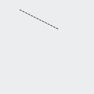
Notice how the duties are separated between Geometry and Path: The Geometry provides the coordinates; the Path provides all other rendering information.
LineGeometry may seem superfluous after the Line and Polyline elements, but unlike Line and Polyline, LineGeometry has two dependency properties of type Point, and these might be very useful as animation targets in some scenarios.
RectangleGeometry defines a property named Rect of type Rect,
a structure that defines a rectangle with four numbers: two numbers
indicate the coordinate point of the upper-left corner and two more
numbers for the rectangle’s size. In XAML you specify these four numbers
sequentially: the x and y coordinates of the upper-left corner, followed by the width and then the height:
<Grid Background="LightCyan">
    <Path Stroke="Maroon"
          StrokeThickness="8"
          Fill="Green">
       <Path.Data>
           <RectangleGeometry
               Rect="100 50 300 200" />
        </Path.Data>
    </Path>
</Grid>

In this example, the bottom-right coordinate of the rectangle is (400, 250). In code, the Rect structure has three constructors that let you specify a Point and a Size, two Point objects, or a string of four numbers as in XAML: (x, y, width, height).
The Bounds property of Geometry is also of type Rect. For the RectangleGeometry above, Bounds would return the same values: (100, 50, 300, 200). For the LineGeometry in the previous example, Bounds would return (100, 50, 200, 100).
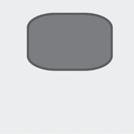
RectangleGeometry also defines RadiusX and RadiusY properties for rounding the corners:
<Grid Background="LightCyan">
    <Path Stroke="Maroon"
          StrokeThickness="8"
          Fill="Green">
        <Path.Data>
            <RectangleGeometry
                Rect="100 50 300 200"
                RadiusX="100"
                RadiusY="50" />
        </Path.Data>
    </Path>
</Grid>
The EllipseGeometry also defines RadiusX and RadiusY properties, but these are for defining the lengths of the two axes. The center of the EllipseGeometry is provided by a property named Center of type Point:
<Grid Background="LightCyan">
    <Path Stroke="Maroon"
          StrokeThickness="8"
          Fill="Green">
        <Path.Data>
            <EllipseGeometry
                Center="250 150"
                RadiusX="150"
                RadiusY="100" />
        </Path.Data>
    </Path>
</Grid>
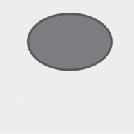
Specifying the center of a circle or ellipse to indicate its location is often a more convenient approach than specifying its upper-left corner (as with the Ellipse element)—particularly considering that ellipses don’t have corners!
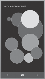
Here’s a little exercise in interactive drawing called TouchAndDrawCircles. When you touch the screen, the program creates a new circle from a Path and an EllipseGeometry.
As you move your finger, the circle gets larger. When you’re finished,
the circle is filled with a random color. If you then touch an existing
circle, you can drag it around the screen.
In the MainPage.xaml file, the content grid is initially empty. The only change I’ve made is to give it a non-null Background so it can generate manipulation events:
Example 1. Silverlight Project: TouchAndDrawCircles File: MainPage.xaml (excerpt)
<Grid x:Name="ContentPanel" Grid.Row="1" Margin="12,0,12,0"
      Background="Transparent" />
|
The code-behind file has just a few fields to keep track of what’s going on:
Example 2. Silverlight Project: TouchAndDrawCircles File: MainPage.xaml.cs (excerpt)
public partial class MainPage : PhoneApplicationPage
{
    Random rand = new Random();
    bool isDrawing, isDragging;
    Path path;
    EllipseGeometry ellipseGeo;
    . . .
}
|
The two Boolean fields indicate a current activity in progress. The Path field is only valid while drawing a new circle; the EllipseGeometry field is valid when drawing a new circle or moving an existing circle.
The override of the OnManipulationStarted method initiates a drawing or dragging operation but doesn’t let more than one to be going on at any time. The OriginalSource property of the event arguments is either a Path element—which means that the user touched one of the existing circles and wants to move it—or the ContentPanel, which initiates a new drawing operation:
Example 3. Silverlight Project: TouchAndDrawCircles File: MainPage.xaml.cs (excerpt)
protected override void OnManipulationStarted(ManipulationStartedEventArgs args)
{
    if (isDrawing || isDragging)
        return;

    if (args.OriginalSource is Path)
    {
        ellipseGeo = (args.OriginalSource as Path).Data as EllipseGeometry;

        isDragging = true;
        args.ManipulationContainer = ContentPanel;
        args.Handled = true;
    }
    else if (args.OriginalSource == ContentPanel)
    {

        ellipseGeo = new EllipseGeometry();
        ellipseGeo.Center = args.ManipulationOrigin;
        path = new Path();
        path.Stroke = this.Resources["PhoneForegroundBrush"] as Brush;
        path.Data = ellipseGeo;
        ContentPanel.Children.Add(path);

        isDrawing = true;
        args.Handled = true;
    }

    base.OnManipulationStarted(args);
}
|
In the XAML file I set the Background of the ContentPanel to Transparent so it would generate Manipulation events. When the OriginalSource property is this Grid, so is the ManipulationContainer, and ManipulationOrigin is relative to the Grid. That’s the point I need for defining the Center of this new EllipseGeometry.
For the dragging operation, the OnManipulationDelta override uses the DeltaManipulation property of the event arguments to modify the Center property of the EllipseGeometry:
Example 4. Silverlight Project: TouchAndDrawCircles File: MainPage.xaml.cs (excerpt)
protected override void OnManipulationDelta(ManipulationDeltaEventArgs args)
{
    if (isDragging)
    {
        Point center = ellipseGeo.Center;
        center.X += args.DeltaManipulation.Translation.X;
        center.Y += args.DeltaManipulation.Translation.Y;
        ellipseGeo.Center = center;

        args.Handled = true;
    }
    else if (isDrawing)
    {
        Point translation = args.CumulativeManipulation.Translation;
        double radius = Math.Max(Math.Abs(translation.X),
                                 Math.Abs(translation.Y));
        ellipseGeo.RadiusX = radius;
        ellipseGeo.RadiusY = radius;

        args.Handled = true;
    }

    base.OnManipulationDelta(args);
}
|
In contrast, for the drawing operation, the method modifies the RadiusX and RadiusY property of the EllipseGeometry. For this it uses the CumulativeManipulationManipulationStarted
event. The reason for the different property is simple: If the user
initiates a drawing operation, and then moves a finger to the left or
up, the translation
factors will be negative. But these negative numbers must become a
positive radius of the circle. It turns out to be easier taking the
absolute value of the total translation factors rather than to modify
existing dimensions. property, which reports the entire manipulation since the
When the finger lifts from the screen, the OnManipulationCompleted event is called for cleanup:
Example 5. Silverlight Project: TouchAndDrawCircles File: MainPage.xaml.cs (excerpt)
protected override void OnManipulationCompleted(ManipulationCompletedEventArgs args)
{
    if (isDragging)
    {
        isDragging = false;
        args.Handled = true;
    }
    else if (isDrawing)
    {
        Color clr = Color.FromArgb(255, (byte)rand.Next(256),
                                        (byte)rand.Next(256),
                                        (byte)rand.Next(256));
        path.Fill = new SolidColorBrush(clr);

        isDrawing = false;
        args.Handled = true;
    }

    base.OnManipulationCompleted(args);
}
|
For the dragging operation, cleanup is simple. But the drawing operation needs to conclude by giving the Path element a random Fill brush.
In actual use, you’ll notice a
little delay between the time your finger begins drawing or dragging a
circle, and the screen reacts. This is a characteristic of the
Manipulation events.
