2. Rendering 3D Primitives
Modern graphics hardware is optimized to render
triangles. You can take it on to prove it to yourself by reviewing a 3D
mathematics text but any 3D object can be modeled to have smooth edges
with enough triangles. Zoom in close enough on a model and the edges can
look jagged, but this does not stray too far from reality in this case
either. As an example, a golf ball is round with bumps, but if you view
it close enough you can see the imperfections, and take comfort in
blaming your errant golf swing on the golf ball's imperfections and not
your golf skills.
This is another aspect of 3D game development that is
art as much as science in managing how many triangles you try to push
through the graphics processor unit (GPU) versus rendering quality at
different zoom levels. More triangles sounds better, but if the frame
rate drops to far over a period of time a game can become unplayable.
We will work with 3D models in a bit, but let's start
out by working with just a few triangles to dip our toe into the water
of 3D game development.
2.1. Creating 3D Primitives
You don't generally create a 3D game using triangle
primitives, but we go through the exercise to define key concepts of 3D
development with the XNA Framework. In the end, when you render a 3D
model created by a graphics artist, you are rendering bunches of
triangles that have been predefined so the concepts covered in this
section translate right over to working with models. To render a 3D
scene in the XNA Framework, follow these steps:
Load your content; in this case, a set of
triangles defined as vertex collections where each vertex is one of the
three points on a triangle.
Load any
textures that will render over the triangles; in this case, to provide a
"skin" that is stretched over the triangle points.
Pass the content to a vertex buffer containing the triangles that the GPU can render.
Define the shader effect that will do the rendering.
Modify the Update method as you did in 2D development to apply translation, rotation, and so on.
Render the vertex buffer using the shader effect in the Draw method.
In the next section, we go through creating a 3D cube that is rendered to the screen.
2.2. From Triangles to Objects
We will draw a 3D cube and apply a color to the cube wireframe. We will
then manipulate different aspects of drawing and movement to help you
understand how 3D development works.
A cube has six square sides connected at 90 degree angles. Figure 4 shows how a cube consists of 12 triangles with two triangles per cube face.
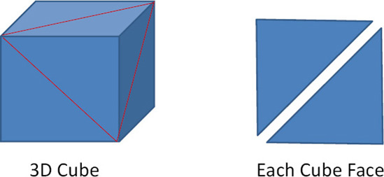
Each side has six indices (three per triangle) and
four vertices per cube face representing each corner of the face. When
thinking about positioning each cube face, remember that an object can
have a coordinate system that goes through the geometric center. In the
case of a cube, it is easily to visualize positioning each face on a 3D
axis as shown in Figure 5.
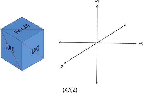
Notice the vector information in Figure 8-7
indicating which axis matches each cube face. Here is a full list of
the "normal" vectors for each face, which is a Vector3 that shoots
straight out of each cube face at a 90 degree angle, which is really
shooting straight out of the two triangles that make up the cube face:
(1,0,0): Positive X axis cube face
(-1,0,0): Negative X axis cube face
(0,1,0): Positive Y axis cube face
(0,-1,0): Negative Y axis cube face
(0,0,1): Positive Z axis cube face
(0,0,-1): Negative Z axis cube face
3D game developers use normal vectors to figure out
positioning between triangles, objects, etc. As an example, if you want
to figure out how to move an object sideways, you figure out the normal
to the front and top vectors to give you the "sideways pointing" vector.
Mathematically, the cross product can find the normal vector between
two vectors As an example, the Z axis is the normal vector to the Y axis
and X axis. The Y axis is the normal to the X axis and Z axis and the X
axis is the normal vector to the Y and Z vector.
Figure 5
makes it easy to visualize the normal vector between the X, Y, and Z
axis. It is a little bit of math to calculate the normal vector between
two vectors. Luckily, the Vector3.Cross method takes two
vectors and finds the normal vector for the two vectors passed in to the
method call. Now we can proceed with building the cube. We add a method
call to CreateCubeObject in the Game.LoadContent() method. We will build up the cube object in the CreateCubeObject method.
To render the cube we use two buffers: one that
contains the vertex information and the other that contains the index
information. Index information allows you to reuse Vertex information.
For example, when two triangles form a square such as a cube face, two
points are shared between the triangles. While you could repeat the
vertex information and have duplicates, for a large model this consumes
precious memory and should be avoided. One way to avoid duplicates is to
store only unique vertices in the vertex buffer and use an index buffer
to represent the triangles that are drawn. Figure 6 shows how the vertex buffer relates to the index buffer.
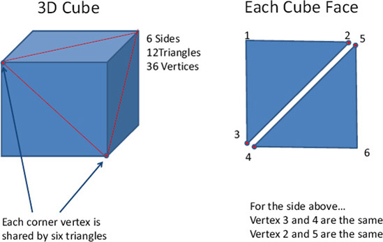
In looking at just the side on the right in Figure 8-8,
the index buffer would have six slots to represent the two triangles,
with three vertices each. However, the vertex buffer would only store
four unique vertices. Here is what the vertex and index buffers would
look like moving left to right around the side shown on the right in Figure 8-8:
Vertex buffer - 1,2,3,6 (Vertices 4 and 5 are duplicates and removed)
Index buffer 1,2,3,2,6,3 (Always six vertices for two triangles)
The actual drawing is done using the index buffer,
because it fully represents each triangle with three vertices per
triangle. When the GPU needs the three points to draw the triangle, it
looks up the actual vertex in the vertex buffer based on the index
buffer with some vertices used multiple times.
In our example, to draw the left / top triangle, the
GPU uses vertices 1,2, and 3. To draw the right/bottom triangle, the GPU
uses 2,6, and 3, reusing two vertices. Although in our example the
memory savings may seem trivial, for a large complex model the savings
can be significant.
2.3. Creating the Cube
Now that you have an understanding of how the vertex
buffer relates to the index buffer, we return to the code to use this
knowledge to create the cube object. Five new members are added to the Game1 class:
VertexBuffer vertexBuffer;
IndexBuffer indexBuffer;

//Lists and variables used to construct vertex and index buffer data
List<VertexPositionNormalTexture> vertices = new List<VertexPositionNormalTexture>();
List<ushort> indices = new List<ushort>();
float size = 3;
The vertices and indices List objects are used to construct the primitive cube model. Once the cube is constructed, the data is loaded into the vertexBuffer and indexBuffer members using the SetData method call. Once loaded, the vertexBuffer and indexBuffer
objects are passed to the graphics device (the GPU) for rendering using
the specified lighting effect. We cover lighting and drawing in a bit.
First let's construct the cube model using the vertices and indicesList objects in the CreateCubeObject method, which is called in the Game1.LoadContent method after the texture is loaded and shown in Listing 1.
Example 1. The Game1.CreateCubeObject Method
private void CreateCubeObject()
{
  // A cube has six faces, each one pointing in a different direction.
  Vector3[] normals =
        {
            new Vector3(0, 0, 1),
            new Vector3(0, 0, −1),
            new Vector3(1, 0, 0),
            new Vector3(−1, 0, 0),
            new Vector3(0, 1, 0),
            new Vector3(0, −1, 0),
        };

  // Create each face in turn.
  foreach (Vector3 normal in normals)
  {
    // Get two vectors perpendicular to the cube face normal and
    //perpendicular to each other
    Vector3 triangleSide1 = new Vector3(normal.Y, normal.Z, normal.X);
    Vector3 triangleSide2 = Vector3.Cross(normal, triangleSide1);

    // Six indices (two triangles) per face
indices.Add((ushort)(vertices.Count + 0));
    indices.Add((ushort)(vertices.Count + 1));
    indices.Add((ushort)(vertices.Count + 2));

    indices.Add((ushort)(vertices.Count + 0));
    indices.Add((ushort)(vertices.Count + 2));
    indices.Add((ushort)(vertices.Count + 3));

    // Four vertices per cube face
    vertices.Add(new VertexPositionNormalTexture(
      (normal - triangleSide1 - triangleSide2) * size / 2, normal,Vector2.One));
    vertices.Add(new VertexPositionNormalTexture(
      (normal - triangleSide1 + triangleSide2) * size / 2, normal,Vector2.One));
    vertices.Add(new VertexPositionNormalTexture(
      (normal + triangleSide1 + triangleSide2) * size / 2, normal,Vector2.One));
    vertices.Add(new VertexPositionNormalTexture(
      (normal + triangleSide1 - triangleSide2) * size / 2, normal,Vector2.One));
  }
}
|
The CreateCubeObject starts by creating the
six vectors that represent each side of the cube. Each vector is normal
to a cube face, positioned along a 3D axis as shown in Figure 5.
With each normal vector, two additional normal
vectors are created that are perpendicular to the normal vector and to
each other. These two new vectors named triangleSide1 and triangleSide2 are used to find the four vertices that represent the cube face corner vertices that are added to the verticesList. The indicesList is updated to add vertex references in the correct order so that the object can be rendered properly.
2.4. Graphics Objects and the Effect Class
We next construct and initialize the graphics objects
and buffers to render our cube primitive. We declare an effect object
of type BasicEffect at the top of Game1.cs. With XNA 4.0,
Microsoft defined several built-in effects classes that draw objects
without having to resort to High Level Shader Language (HLSL) coding.
Windows Phone 7 does not support HLSL so we do not dive into HLSL
development but in short the language allows developers to directly
program the GPU to crate dazzling visual effects.
It may seem like a major limitation to not be able to
program in HLSL but the built in Effect class descendants provide
several benefits:
Cross-platform support is simplified by using
the Effect class objects. This is known as the "reach" profile in XNA
Game Studio 4.0.
The Effect class objects are highly configurable, allowing a wide-range of visual effects programming in C#.
Developers do not have to learn yet another language in HLSL.
Table 1 has a list of available effect classes in XNA Game Studio 4.0.
Table 1. Configurable Effect Classes in the XNA Framework
| Effect | Description |
|---|
| AlphaTest | Contains a configurable effect that supports alpha testing. |
| BasicEffect | Contains a basic rendering effect. |
| DualTextureEffect | Contains a configurable effect that supports two-layer multitexturing. |
| Effect | Used to set and query effects, and to choose techniques that are applied when rendering. |
| EnvironmentMapEffect | Contains a configurable effect that supports environment mapping. |
| SkinnedEffect | Contains a configurable effect for rendering skinned character models. |
Each Effect class in Table 1
has several configurable "knobs" that provide developers a wide range
of control without having to delve into HLSL. This link has more
information and samples on the various available Effect classes:
http://create.msdn.com/en-us/education/catalog/?contenttype=0&devarea=14&sort=2
The ConstructGraphicsObjectsForDrawingCube method initializes the graphics objects and the BasicEffect object:
private void ConstructGraphicsObjectsForDrawingCube()
{
  // Create a vertex buffer, and copy the cube vertex data into it
  vertexBuffer = new VertexBuffer(graphics.GraphicsDevice,
                                  typeof(VertexPositionNormalTexture),
                                  vertices.Count, BufferUsage.None);
  vertexBuffer.SetData(vertices.ToArray());

  // Create an index buffer, and copy the cube index data into it.
  indexBuffer = new IndexBuffer(graphics.GraphicsDevice, typeof(ushort),
                                indices.Count, BufferUsage.None);
  indexBuffer.SetData(indices.ToArray());

  // Create a BasicEffect, which will be used to render the primitive.
  basicEffect = new BasicEffect(graphics.GraphicsDevice);
  basicEffect.EnableDefaultLighting();
  basicEffect.PreferPerPixelLighting = true;
}
The vertex and index data calculated in the CreateCubeObject method are loaded into the vertexBuffer and indexBuffer objects, respectively. The BasicEffect is instantiated next. We discuss effects in more detail later, but essentially the BasicEffect object provides the environmental effects for the scene such as lighting and shading.
2.5. Drawing the Cube
To draw the cube we need several additional member variables that are added at the top of Game1.cs.
float yaw = .5f;
float pitch = .5f;
float roll = .5f;
Vector3 cameraPosition = new Vector3(0, 0, 10f);
The last method related to our cube is the Game1.DrawCubePrimitive method listed here:
private void DrawCubePrimitive (Matrix world, Matrix view, Matrix projection, Color color)
{
  // Set BasicEffect parameters.
  basicEffect.World = world;
  basicEffect.View = view;
  basicEffect.Projection = projection;
  basicEffect.DiffuseColor = color.ToVector3();
  basicEffect.Alpha = color.A / 255.0f;

  GraphicsDevice graphicsDevice = basicEffect.GraphicsDevice;
  // Set our vertex declaration, vertex buffer, and index buffer.
  graphicsDevice.SetVertexBuffer(vertexBuffer);
  graphicsDevice.Indices = indexBuffer;

  foreach (EffectPass effectPass in basicEffect.CurrentTechnique.Passes)
  {
    effectPass.Apply();
    int primitiveCount = indices.Count / 3;
    graphicsDevice.DrawIndexedPrimitives(
      PrimitiveType.TriangleList, 0, 0,vertices.Count, 0, primitiveCount);
  }
}
The DrawCubePrimitive method is called in the Game1.Draw method. This method instantiates the graphicsDevice
object and passes in the calculated vertex and index information for
rendering. Depending on the effect used, one or more passes are executed
to create the scene, drawing the triangle primitives using the graphicsDevice.DrawIndexedPrimitives method.
The cube is ready for rendering within a 3D scene. We next move to incorporating the cube code into an XNA Framework game.
