RasterizerState
The RasterizerState
object enables you to have a measure of control over this process in a
variety of ways. To see the kinds of controls you have, create a new
Game project and add the depthmodel.fbx file to your Content project.
Then, declare your instance variables for the game:
Model model;
Matrix proj;
Matrix view;
RasterizerState wireframe;
RasterizerState scissor;
The RasterizerState
class has a few static members that you can use, but you also use two
extra states in this example. Create the following objects in your LoadContent method:
proj = Matrix.CreatePerspectiveFieldOfView(MathHelper.PiOver4,
    GraphicsDevice.Viewport.AspectRatio, 1.0f, 100.0f);
view = Matrix.CreateLookAt(new Vector3(0, 3, 20), Vector3.Zero, Vector3.Up);
model = Content.Load<Model>("depthmodel");
foreach (ModelMesh mm in model.Meshes)
{
    foreach (Effect e in mm.Effects)
    {
        IEffectLights iel = e as IEffectLights;
        if (iel != null)
        {
            iel.EnableDefaultLighting();
        }
    }
}
wireframe = new RasterizerState();
wireframe.FillMode = FillMode.WireFrame;
scissor = new RasterizerState();
scissor.ScissorTestEnable = true;
After the matrices and the
model are created and the lighting initialized, create your two needed
state objects. The first changes the fill mode to WireFrame. The only other option for this property is Solid, which is the default. When you’re rending an object with WireFrame enabled, you see only the triangles rendered, but not the pixels inside of them. For the next option, turn on the ScissorTestEnable (the default is false). This is discussed in a moment when you see what it does! Now replace your Draw method with the following:
protected override void Draw(GameTime gameTime)
{
    GraphicsDevice.Clear(Color.CornflowerBlue);
    float time = (float)gameTime.TotalGameTime.TotalSeconds;
    Matrix rotation = Matrix.CreateRotationZ(time) *
        Matrix.CreateRotationY(time / 4.0f);
    Matrix world = Matrix.CreateScale(0.25f) * rotation;
    // Set some rasterizer states
    GraphicsDevice.RasterizerState = RasterizerState.CullCounterClockwise;
    model.Draw(world * Matrix.CreateTranslation(-6, 0, 0), view, proj);
    GraphicsDevice.RasterizerState = wireframe;
    model.Draw(world * Matrix.CreateTranslation(6, 0, 0), view, proj);
    GraphicsDevice.RasterizerState = RasterizerState.CullClockwise;
    model.Draw(world * Matrix.CreateTranslation(0, -6, 0), view, proj);
    GraphicsDevice.RasterizerState = scissor;
    GraphicsDevice.ScissorRectangle = new Rectangle(0, 0,
        GraphicsDevice.Viewport.Width, GraphicsDevice.Viewport.Height / 8);
    model.Draw(world * Matrix.CreateTranslation(0, 6, 0), view, proj);
}
Here,
you draw the model four different times, each time with a different
rasterization setting and in a different location. The first draw call
uses the static RasterizerState.CullCounterClockwise member, which sets the CullMode property of the state to CullCounterClockwise.
This also happens to be the default, so this first object appears
exactly as it normally would if you hadn’t set this state. So what
exactly does CullMode mean, and what does it do?
When the device renders a
triangle, it has two sides, but for most 3D models, you can see only one
side of a given triangle. So each triangle has a “front” face, the side
you expect to see, and a “back” face, the side you probably won’t see.
The CullMode property tells the device
to rasterize only pixels for one of those faces. This is determined by
the vertices of the triangles “winding order.” Triangles have either a
winding order of clockwise, or counterclockwise. CullCounterClockwise
tells the device to cull (remove) faces with a winding order of
counterclockwise. The default winding order for XNA applications is that
the front-facing triangles are wound clockwise and back-facing
triangles are wound-counterclockwise.
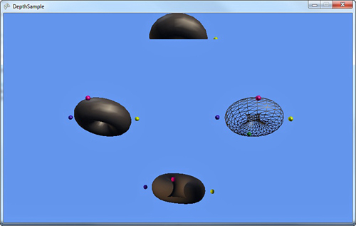
Next, draw the model to the
right with the wireframe state. As you expect, the model is not drawn
solid, but instead with the triangles being drawn, but not the pixels
inside of it. This mode is called wireframe.
The bottom model is drawn
with the opposite culling mode. While running the application, notice
that it looks odd. This is because it’s rendering only the “wrong side”
of each triangle, so you see what the model looks like almost inside
out. You can also use the built-in static member RasterizerState.CullNone to render both sides of each triangle.
The last model (the one drawn
at the top of the screen) simply turns on the scissor test. The scissor
test tells the device to not render any pixels that are outside the ScissorRectangle
property of the device (which by default is the same size as the
currently applied render target or back buffer). In this example, you
set the rectangle to be the entire width of the screen, but only the
upper eighth portion, which causes the model to be cut in half. Why are
the other three models still showing despite the fact you told the
device to render only in the upper eighth of the screen? The other three
models were rendered with a state that had the scissor test turned off.
When you run the example, you see each of the four rasterizer states, as shown in Figure 2.