Pierre Etienne Bézier (1910–1999) was an engineer at
the French automobile company Renault from 1933 to 1975. During the
1960s the company started switching over from designing car bodies with
clay to using computer-assisted design. The system required mathematical
descriptions of curves that engineers could manipulate without knowing
the underlying mathematics. From this work came the curve that now bears
Pierre Bézier’s name.
The Bézier curve is a spline,
which is a type of curve used to approximate discrete data with a smooth
continuous function. Silverlight supports the standard two-dimensional
form of the cubic Bézier curve but also a quadratic Bézier curve that is somewhat simpler
and faster.
The quadratic
Bézier curve is defined by three points, commonly denoted as p0, p1,
and p2. The curve starts at
p0 and ends at p2. The point p1 is known as a control point. The
curve usually does not pass through p1.
Instead, p1
functions like a magnet pulling the curve towards it. At p0, the
curve is tangent to (and in the same direction as) the line from p0 to p1,
and at p3 the curve is tangent to (and in the same direction as) the line
from p2 to p3.
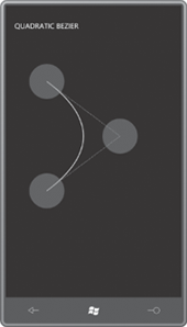
Perhaps the best way to
become familiar with Bézier curves is to experiment with them. The QuadraticBezier
program draws a single Bézier curve but lets you manipulate the three
points to see what happens.
The XAML file assembles four Path elements and a Polyline in the single-cell Grid. The first Path is the quadratic Bézier itself. Notice that p0 is provided
by the StartPoint property of PathFigure, while p1,
and p2 correspond to the Point1 and Point2
properties of QuadraticBezierSegment:
Example 1. Silverlight
Project: QuadraticBezier File: MainPage.xaml (excerpt)
<Grid x:Name="ContentPanel" Grid.Row="1" Margin="12,0,12,0">
    <Path Stroke="{StaticResource PhoneForegroundBrush}"
         StrokeThickness="2">
       <Path.Data>
           <PathGeometry>
               <PathFigure x:Name="pathFig"
                           StartPoint="100 100">
                   <QuadraticBezierSegment x:Name="pathSeg"
                                           Point1="300 250"
                                           Point2="100 400" />
               </PathFigure>
           </PathGeometry>
       </Path.Data>
   </Path>

   <Polyline Name="ctrlLine"
             Stroke="{StaticResource PhoneForegroundBrush}"
             StrokeDashArray="2 2"
             Points="100 100, 300 250, 100 400" />

   <Path Name="pt0Dragger"
         Fill="{StaticResource PhoneAccentBrush}"
         Opacity="0.5">
       <Path.Data>
           <EllipseGeometry x:Name="pt0Ellipse"
                            Center="100 100"
                            RadiusX="48"
                            RadiusY="48" />
       </Path.Data>
   </Path>

   <Path Name="pt1Dragger"
         Fill="{StaticResource PhoneAccentBrush}"
         Opacity="0.5">
       <Path.Data>
           <EllipseGeometry x:Name="pt1Ellipse"
                            Center="300 250"
                            RadiusX="48"
                            RadiusY="48" />
       </Path.Data>
   </Path>

   <Path Name="pt2Dragger"
         Fill="{StaticResource PhoneAccentBrush}"
         Opacity="0.5">
       <Path.Data>
           <EllipseGeometry x:Name="pt2Ellipse"
                            Center="100 400"
                            RadiusX="48"
                            RadiusY="48" />
        </Path.Data>
    </Path>
</Grid>
|
The Polyline element draws a dotted line from the two end
points to the control point. The remaining three Path elements are
“draggers,” that is, they let you drag any of the three points. The
initial screen looks like this:
The code-behind file provides all the dragging
logic. Because Silverlight for Windows Phone does not support bindings
for properties not defined by FrameworkElement derivatives, I wasn’t able to hook all
the corresponding points together in the XAML file. Instead, they have
to be set individually in the Manipulation
overrides:
Example 2. Silverlight
Project: QuadraticBezier File: MainPage.xaml.cs (excerpt)
protected override void OnManipulationStarted(ManipulationStartedEventArgs args)
{
    if (args.OriginalSource == pt0Dragger ||
        args.OriginalSource == pt1Dragger ||
        args.OriginalSource == pt2Dragger)
    {
        args.ManipulationContainer = ContentPanel;
        args.Handled = true;
    }
    base.OnManipulationStarted(args);
}

protected override void OnManipulationDelta(ManipulationDeltaEventArgs args)
{
    Point translate = args.DeltaManipulation.Translation;

    if (args.OriginalSource == pt0Dragger)
    {
        pathFig.StartPoint = Move(pathFig.StartPoint, translate);
        ctrlLine.Points[0] = Move(ctrlLine.Points[0], translate);
        pt0Ellipse.Center = Move(pt0Ellipse.Center, translate);
        args.Handled = true;
    }
    else if (args.OriginalSource == pt1Dragger)
    {
        pathSeg.Point1 = Move(pathSeg.Point1, translate);
        ctrlLine.Points[1] = Move(ctrlLine.Points[1], translate);
        pt1Ellipse.Center = Move(pt1Ellipse.Center, translate);
        args.Handled = true;
     }
     else if (args.OriginalSource == pt2Dragger)
     {
        pathSeg.Point2 = Move(pathSeg.Point2, translate);
        ctrlLine.Points[2] = Move(ctrlLine.Points[2], translate);
        pt2Ellipse.Center = Move(pt2Ellipse.Center, translate);
        args.Handled = true;
     }
     base.OnManipulationDelta(args);
}

Point Move(Point point, Point translate)
{
    return new Point(point.X + translate.X, point.Y + translate.Y);
}
|
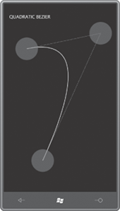
Being a quadratic,
this version of the Bézier curve makes only a single turn, and it is
extremely well behaved:
If you ever need them, the parametric formulas used to construct the quadratic Bézier are:


for t = 0 to 1,
where p0 = (x0, y0)
and so forth.
The cubic Bézier spline is more standard, and has two control
points rather than just one. The curve is defined by four points
commonly labeled p0, p1, p2, and p3. The curve begins at p0
and ends at p3. At p0 the
curve is tangent to (and in the same direction as) a line from p0 to p1,
and at p3
the curve is tangent to the line from p3p2. The parametric equations
describing the curve are:
to


For the CubicBezier program I took a little different approach. In
an attempt to simplify it just a bit, I defined a UserControl derivative named PointDragger. The
PointDragger.xaml file defines a visual tree consisting of just a Grid containing a Path
with an Opacity of 0.5 and an EllipseGeometry with no Center point:
Example 3. Silverlight
Project: CubicBezier File: PointDragger.xaml
<UserControl
    x:Class="CubicBezier.PointDragger"
    xmlns="http://schemas.microsoft.com/winfx/2006/xaml/presentation"
    xmlns:x="http://schemas.microsoft.com/winfx/2006/xaml">

    <Grid x:Name="LayoutRoot">
        <Path Fill="{StaticResource PhoneAccentBrush}"
              Opacity="0.5">
            <Path.Data>
                <EllipseGeometry x:Name="ellipseGeometry"
                                 RadiusX="48"
                                 RadiusY="48" />
            </Path.Data>
        </Path>
    </Grid>
</UserControl>
|
The code-behind file
defines a dependency property named Point
of type Point, and fires a PointChanged event
when the value changes. The property-changed handler is also
responsible for setting the value on the EllipseGeometry
defined in the XAML file:
Example 4. Silverlight
Project: CubicBezier File: PointDragger.xaml.cs (excerpt)
public partial class PointDragger : UserControl
{
    public static readonly DependencyProperty PointProperty =
        DependencyProperty.Register("Point",
            typeof(Point),
            typeof(PointDragger),
            new PropertyMetadata(OnPointChanged));
     public event RoutedPropertyChangedEventHandler<Point> PointChanged;

    public PointDragger()
    {
        InitializeComponent();
    }

    public Point Point
    {
        set { SetValue(PointProperty, value); }
        get { return (Point)GetValue(PointProperty); }
    }

    . . .

    static void OnPointChanged(DependencyObject obj,
                               DependencyPropertyChangedEventArgs args)
    {
        (obj as PointDragger).OnPointChanged((Point)args.OldValue,
                                             (Point)args.NewValue);
    }

    protected virtual void OnPointChanged(Point oldValue, Point newValue)
    {
        ellipseGeometry.Center = newValue;

        if (PointChanged != null)
            PointChanged(this,
                new RoutedPropertyChangedEventArgs<Point>(oldValue, newValue));
    }
}
|
The PointDragger
class also handles its own Manipulation
events, which (compared with the ones in QuadraticBezier) become very
simple:
Example 5. Silverlight
Project: CubicBezier File: PointDragger.xaml.cs (excerpt)
protected override void OnManipulationStarted(ManipulationStartedEventArgs args)
{
    args.ManipulationContainer = VisualTreeHelper.GetParent(this) as UIElement;
    args.Handled = true;
    base.OnManipulationStarted(args);
}

protected override void OnManipulationDelta(ManipulationDeltaEventArgs args)
{
    Point translate = args.DeltaManipulation.Translation;
    this.Point = new Point(this.Point.X + translate.X, this.Point.Y + translate.Y);
    args.Handled = true;
    base.OnManipulationDelta(args);
}
|
The MainPage.xaml file defines a Path with a BezierSegment,
two dotted Polyline
elements for the tangent lines, and four instances of PointDragger. The BezierSegment class
defines properties named Point1, Point2,
and Point3
for the two control points and the endpoint:
Example 6. Silverlight
Project: CubicBezier File: MainPage.xaml (excerpt)
<Grid x:Name="ContentPanel" Grid.Row="1" Margin="12,0,12,0">
    <Path Stroke="{StaticResource PhoneForegroundBrush}"
          StrokeThickness="2">
        <Path.Data>
            <PathGeometry>
                <PathFigure x:Name="pathFig"
                            StartPoint="100 100">
                    <BezierSegment x:Name="pathSeg"
                                   Point1="300 100"
                                   Point2="300 400"
                                   Point3="100 400" />
                </PathFigure>
            </PathGeometry>
        </Path.Data>
    </Path>

    <Polyline Name="ctrl1Line"
              Stroke="{StaticResource PhoneForegroundBrush}"
              StrokeDashArray="2 2"
              Points="100 100, 300 100" />

    <Polyline Name="ctrl2Line"
              Stroke="{StaticResource PhoneForegroundBrush}"
              StrokeDashArray="2 2"
              Points="300 400, 100 400" />

    <local:PointDragger x:Name="pt0Dragger"
                        Point="100 100"
                        PointChanged="OnPointDraggerPointChanged" />

    <local:PointDragger x:Name="pt1Dragger"
                        Point="300 100"
                        PointChanged="OnPointDraggerPointChanged" />

    <local:PointDragger x:Name="pt2Dragger"
                        Point="300 400"
                        PointChanged="OnPointDraggerPointChanged" />

    <local:PointDragger x:Name="pt3Dragger"
                        Point="100 400"
                        PointChanged="OnPointDraggerPointChanged" />
</Grid>
|
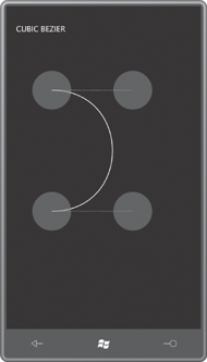
The initial screen looks like
this:
Notice the PointChanged
event handlers on the PointDragger controls. Implementing that handler is pretty
much the only thing left for MainPage.xaml.cs to do:
Example 7. Silverlight
Project: CubicBezier File: MainPage.xaml.cs (excerpt)
void OnPointDraggerPointChanged(object sender,
                                RoutedPropertyChangedEventArgs<Point> args)
{
    Point translate = new Point(args.NewValue.X - args.OldValue.X,
                                args.NewValue.Y - args.OldValue.Y);
    if (sender == pt0Dragger)
    {
        pathFig.StartPoint = Move(pathFig.StartPoint, translate);
        ctrl1Line.Points[0] = Move(ctrl1Line.Points[0], translate);
    }
    else if (sender == pt1Dragger)
    {
        pathSeg.Point1 = Move(pathSeg.Point1, translate);
        ctrl1Line.Points[1] = Move(ctrl1Line.Points[1], translate);
    }
    else if (sender == pt2Dragger)
    {
        pathSeg.Point2 = Move(pathSeg.Point2, translate);
        ctrl2Line.Points[0] = Move(ctrl2Line.Points[0], translate);
    }
    else if (sender == pt3Dragger)
    {
        pathSeg.Point3 = Move(pathSeg.Point3, translate);
        ctrl2Line.Points[1] = Move(ctrl2Line.Points[1], translate);
    }
}

Point Move(Point point, Point translate)
{
    return new Point(point.X + translate.X, point.Y + translate.Y);
}
|
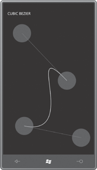
As you play around with the program, you might notice that the curve
always stays confined within a four-side polygon defined by the two end
points and the two control points. (It’s called a “convex hull” in
Bézier circles.). This version of the Bézier curve is a cubic, so the curve can make two turns:
Besides QuadraticBezierSegment
and BezierSegment to define single
Bézier curves, you can also use PolyQuadraticBezierSegment and PolyBezierSegment for defining a series of Bézier
curves. Each curve begins at the point the previous one ends. Each of
these classes contains a property named Points
of type PointCollection.
For PolyQuadraticBezierSegment,
the number of Point objects in the Points collection
must be a multiple of 2. The first, third, fifth, and so forth members
of the collection are control points. For PolyBezierSegment, the number of points is a multiple of 3.
When connecting multiple
Bézier curves, the end point of one curve becomes the begin point of the
next curve. The composite curve is smooth at this point only if that
point and the two control points on either side are collinear, that is,
lie on the same line.
