The link between your computer and your modem is the serial port (also known as a COM port or RS-232
port). For an external modem, this link
usually comes in the form of a serial cable that runs from the port to
an interface in the back of the modem. The exception is the pocket
modem, which usually plugs into the serial port directly. For internal
and PC Card modems, the serial port is built right into the modem’s
circuitry.
They’re called serial ports because they transmit and receive data
one bit at a time, in a series. (This is opposed to working with data in
parallel,
in which multiple bits are transmitted simultaneously.) As such, serial
ports can be used by many kinds of devices that require two-way
communication, such as mice, infrared adapters, bar code scanners, and,
of course, modems.
Serial Port Pin
Configurations
Like most computer
interfaces, serial ports send and receive data and signals via wires
that correspond to single bits. For a serial port, these wires are metal
pins that come in two configurations: 9-pin and 25-pin, as illustrated
in Figure 1. From the context of modem
communications, there is no essential difference between the 9-pin and
25-pin connectors, other than their layout. Table 1
shows the pin assignments for the 9-pin connector, and Table 2 shows the partial pin assignments for the
25-pin connector (the other pins can be safely ignored).
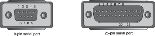
Table 1. Pin Assignments for a 9-Pin Serial
Port Connector
| Pin Number | Signal |
|---|
| 1 | Carrier Detect (CD) |
| 2 | Receive Data (RD) |
| 3 | Transmit Data (TD) |
| 4 | Data Terminal Ready (DTR) |
| 5 | Signal Ground |
| 6 | Data Set Ready (DSR) |
| 7 | Request To Send (RTS) |
| 8 | Clear To Send (CTS) |
| 9 | Ring Indicator |
Table 2. Partial
Pin Assignments for a 25-Pin Serial Port Connector
| Pin Number | Signal |
|---|
| 2 | Transmit Data (TD) |
| 3 | Receive Data (RD) |
| 4 | Request To Send (RTS) |
| 5 | Clear To Send (CTS) |
| 6 | Data Set Ready (DSR) |
| 7 | Signal Ground |
| 8 | Carrier Detect (CD) |
| 20 | Data Terminal Ready (DTR) |
| 22 | Ring Indicator |
The key pins in both layouts
are Transmit Data (TD) and Receive Data (RD). The computer uses the TD
pin to send the individual bits of outgoing serial data to the modem.
For incoming data, the modem uses the RD pin to get the bits into the
computer.
The UART: The
Heart of the Serial Port
You might be wondering
how the computer’s processor and the serial port can possibly get along
with each other. After all, the CPU deals with data in parallel: the
eight bits (one byte) that are required to represent a single character
of information. I’ve just told you, however, that serial ports are
one-bit wonders. How do you reconcile these seemingly incompatible ways
of looking at data?
The answer is a
special chip that resides inside every serial port (or sometimes on the
computer’s motherboard): the Universal
Asynchronous Receiver/TransmitterUART). (For an internal or PC Card modem, the UART chip
sits on the card itself.) It’s the UART’s job, among other things, to
take the computer’s native parallel data and convert it into a series of
bits that can be spit out of the serial port’s TD line. On the other
end, individual bits streaming into the destination serial port’s RD
line are reassembled by the UART into the parallel format that the
processor prefers. (
It’s clear, then, that
the role of the UART in data communications is crucial. In fact, the
UART is often the source of transmission bottlenecks that can hold up
the entire process. To see why, consider what happens when serial data
arrives via the modem. The UART assembles the incoming bits until it has
a full byte, and it stores this byte in a special memory buffer. It
then notifies the CPU—by generating an interrupt request—that data is
waiting. Under ideal conditions, the CPU grabs the data from the buffer
immediately, the UART processes the next byte, and the cycle repeats.
However, what if the CPU is busy with some other task when it receives
the interrupt request? The UART continues processing the incoming bits,
and if the processor can’t get to the buffered data in time, the UART
simply overwrites the existing buffer with the new data. This means, at
best, that the lost byte must be retransmitted, and the overall
performance of the download suffers as a result. (At worst, you might
lose the character altogether!)
This isn’t usually a
problem at relatively slow data transfer rates (for example, up to
9,600bps), but it can cause all kinds of problems with modern modems
running at up to 56,600bps. To prevent these overruns, you need a UART
that can keep up with the deluge. Here’s a summary of the various UART
types and their suitability for fast data transfer rates:
| 8250 | This
was the chip used in the original IBM PC XT. Its design calls for a
one-byte data buffer, so it isn’t suitable for high-speed transfers. |
| 16450 | This
was the chip used in the IBM PC AT and compatible machines. Although it
sported some improvements over 8250 (essentially the capability of
working with computers that have higher internal clock speeds), it still
used the one-byte data buffer, so it too is limited to 9,600bps. |
| 16550 | This
chip represented a huge improvement over its predecessors. The major
innovation was a 16-byte FIFO
(first in, first out) buffer that enabled the UART to handle high-speed data
transfers, and reduced retransmissions and dropped characters. Also, the
16550 had a variable interrupt trigger that the user could configure to
send an interrupt to the CPU when the buffer reached a certain number
of bytes. (You’ll see later that Windows XP lets you configure this
trigger.) The 16550, however, had a defective FIFO buffer that often
caused data loss. |
| 16550A | This is a replacement chip
that fixes the bugs in the 16550 but is otherwise identical. The 16550A
(or the updated 16550AF, 16550AN, or 16550AFN) is the chip of choice for
modems that support data transfer rates of 14,400bps and up. Almost all
modern systems have this type of UART. |
