1. Copying and Pasting Shapes
One of the simplest but nicest
enhancements in Visio 2010 is that pasting copied shapes works more
logically. For example, if you copy one or more shapes from Page-1 and
then paste them onto Page-2, Visio will paste them in the same position
on Page-2 that they were on Page-1. In previous versions, Visio always
pasted shapes into the center of the drawing window. Occasionally this
was what you wanted, but as often as not, this placement required
additional dragging and nudging.
In this exercise, you will create a new page and copy the shapes from Page-1 to Page-2.
Select all of the shapes on Page-1, and press Ctrl+C to copy them.
Insert Page

To the right of the Page-1 name tab below the drawing page, click the Insert Page button.
Press Ctrl+V to paste the shapes onto Page-2. Notice that they are placed in the identical position on the page that they occupy on Page-1.
Click the Page-1 name tab to return to that page.
Note:
Save your changes to the Basic shapes drawing but leave it open if you are continuing with the next exercise.
There are two other enhancements to the paste logic in Visio 2010.
You can paste to a
specific place: right-click at the location on the page where you would
like to paste, and select Paste from the context menu. Visio will center
the pasted shape(s) at the cursor location.
It’s
easier to use Paste Special: right-click anywhere on the drawing page
and select Paste Special from the context menu; Visio opens the Paste
Special dialog box. (In previous versions of Visio, you were required to
use the Edit menu to access the Paste Special dialog box.)
2. Connecting Shapes with Lines
Visio shapes are either one dimensional (1-D) or two dimensional (2-D). 1-D shapes act like lines, with endpoints that can be attached to other shapes. 2-D
shapes behave like polygons, with edges and an interior. However,
appearances can be deceiving because some shapes that appear to be
two-dimensional may actually be 1-D shapes in Visio. The reverse can also be true.
In this exercise, you will connect
a variety of 1-D shapes to 2-D shapes.
Line

On the Home tab, in the Tools group, click the Line tool. Notice that the cursor changes to a plus sign with a diagonal line to the lower right.
Warning:
Important
The
Line tool is one of six tools located on a menu immediately to the
right of the Pointer Tool. If the Line tool is not visible, click the
arrow next to whichever tool is displayed on the button.
Point
near any of the five shapes toward the top of the page. Notice that
little blue Xs appear on the edges and/or in the center of the shapes.
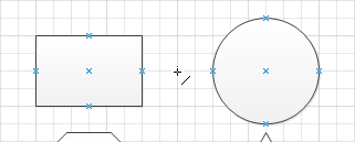
The blue Xs are connection points. They appear whenever you move near them with a 1-D shape or a tool like the Line tool.
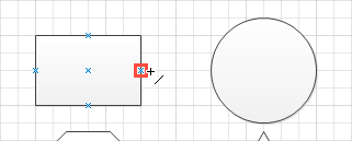
Move
the cursor near a connection point and notice that a red square
appears. The square indicates that you can click on it to glue one end
of the line to the connection point.
Drag
from the connection point on the right end of the rectangle to the
connection point on the left edge of the circle, and then release the
mouse button.
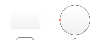
You have drawn a line that is
glued to the edges of the two shapes. Notice that the handle on the
originating end of the glued line shows a white box with a red outline
and the handle on the destination end shows a solid red box.
Draw another line above the rectangle but do not glue either end to a shape.
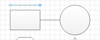
The line shows a white square with a blue outline on the originating end and a solid blue square on the destination end.
Tip:
The color distinction
between the unglued line ends in this step and the glued line ends in
the previous step is an important one in Visio. Although it’s quite
obvious in these two examples whether the line ends are connected, in
the next step, you’ll see an example in which the color of the line end
is very helpful in determining connectedness.
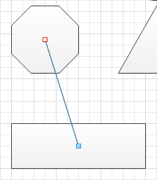
Use the Line tool to draw a line from the connection point at the center of the octagon to the long rectangle below it.
The
long rectangle that you created with the drawing tool in a previous
exercise does not contain any connection points; consequently, you can
only drop the end of the line onto the shape and can’t glue it. You can
confirm which ends are glued by comparing the color and pattern at each
end of this line with the handles in the previous two examples.
Pointer Tool

On the Home tab, in the Tools group, click the Pointer Tool.
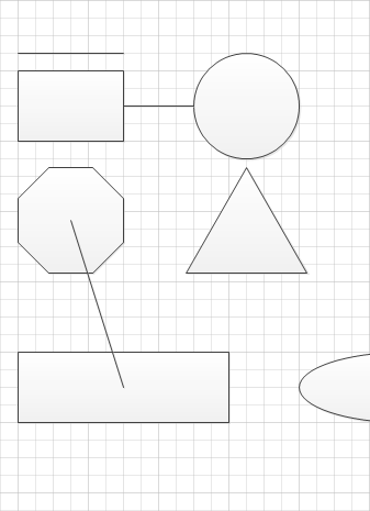
Drag
the circle up and to the right. Drag the long rectangle below the
octagon down. The following two graphics show the before (left) and
after (right).
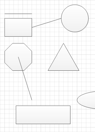
The
line that is glued to the rectangle and circle stays attached at the
connection points. The line that was touching the long rectangle but was
not glued becomes separated when you move the rectangle.
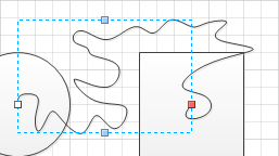
Freeform

On the Home tab, in the Tools group, click the Freeform tool. Notice that the cursor changes to a plus sign with a squiggly line to the lower right.
Click
the connection point in the center of the circle and move the cursor
randomly, eventually arriving at the connection point at the center of
the square. Notice that the line develops a bend each time you make a
significant change in direction.
There are several important things to note about the line you’ve drawn:
If
you glued both ends of the line to connection points, the curved line
behaves just like the straight line: if you move the shapes, the line
will follow. In the case of the freeform line, the line will also retain
its unique set of curves. (Try moving the shapes attached to your
squiggly line; the results are often quite interesting.)
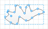
There
are blue circles at the key points of curvature along the line. These
circles are actually handles that you can drag to reshape the line.
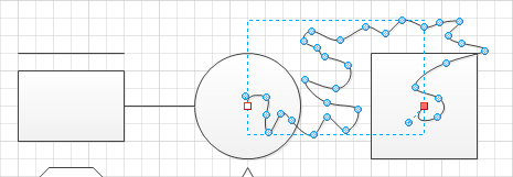
The
blue circles are only visible if you select the shape with one of the
line tools (Line, Freeform, Arc, or Pencil). If you select it with the
Pointer Tool or the Rectangle or Ellipse tools, only the endpoints are
visible, as shown in the following graphic.
In a blank area of the drawing page, draw a freeform line but be sure to end it at exactly the same point that you started.
Notice the important
difference from the line you drew in the previous step: as soon as you
finish “closing the loop,” Visio applies a fill to your new shape and no
square handles appear at the beginning and end of the line. By ending
your line at the same place you began, you’ve drawn a 2-D shape, not a
1-D shape.
