You learned about four
types of 1-D shapes that you can create with the Visio line tools.
Although several of those line types can include curves or bends, those
features are only present if you place them there. Visio also offers a
line called a dynamic connector.
When you use a dynamic connector, Visio automatically adds and removes
bends in the line based on the positions of the shapes to which it’s
glued.
In
this exercise, you will perform some of the same steps you completed in
the previous exercise but will use dynamic connectors in order to
understand the differences in behavior.
Click the Page-2 tab at the bottom of the drawing page to move to Page-2.
Connector

On the Home tab, in the Tools group, click the Connector button. Notice that the cursor changes to a black arrow and there is an arrow with two right-angle bends below it.
Just
as with the line tools you used in the preceding exercise, you’ll see
that connection points appear on various shapes as you point near them
with the Connector Tool.
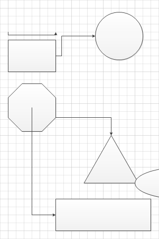
Drag
from the connection point on the right center of the upper rectangle to
the connection point on the left edge of the circle, and then release
the mouse button.
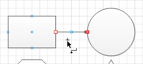
Just as in the preceding
exercise, the line you’ve drawn shows red handles at its endpoints.
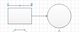
However, unlike the previous line, a dynamic connector has an arrowhead
on its destination end by default. The arrowhead in this graphic is
largely obscured by the red handle, but when the dynamic connector is
deselected, as in the following graphic, the arrowhead is visible.
Draw
another dynamic connector above the rectangle but do not glue either
end to a shape. Even if you try to draw the connector as a straight
line, notice that it appears to have a mind of its own. This will turn
out to be one of the most useful characteristics of a dynamic connector,
as you will see in subsequent steps in this exercise.
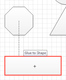
Use
the dynamic connector to draw a line from the connection point at the
center of the octagon to the center of the long rectangle below it.
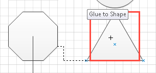
Something
very different happens compared to the preceding exercise where you
performed the same step with the line tool. Even though the long
rectangle does not contain any connection points, you can still glue a
dynamic connector to the shape. Visio provides two visual cues: pop-up
text appears above the rectangle, as shown in the following graphic on
the left, and the border of the shape is outlined in red. When you
release the mouse button, the connector appears as shown in the graphic
on the right.
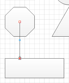
You’ve just used something Visio calls dynamic glue
to attach a connector to a shape without any connection points. As you
will discover in the next step, you can do the same thing even if a
shape has connection points, merely by pointing to a part of the shape
where there aren’t any.
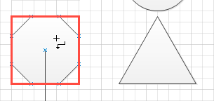
Point
to the interior of the octagon until the border of the selection
rectangle lights up in red (the following graphic on the left shows the
cursor inside the selection rectangle). Drag until the border of the
triangle turns red and the words Glue to Shape appear, as shown on the right. Don’t release the mouse button yet.
In the graphic on the right,
even though the cursor (the plus sign) is above the center of the
triangle, the dynamic connector once again seems to have a mind of its
own and is connecting to the lower-left corner.
Release the mouse button to observe that the dynamic connector has glued itself to points along the edges of the two shapes.
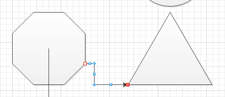
Tip:
Notice
the blue control handles at each bend and in the middle of each segment
of a dynamic connector. You can drag any of these control handles to
relocate individual segments of the dynamic connector.
With a few final steps, you will see the real value of a dynamic connector and learn the difference between static glue and dynamic glue.
Pointer Tool

On the Home tab, in the Tools group, click the Pointer Tool.
Drag
the circle up and to the right; drag the long rectangle below the
octagon down and to the right; drag the triangle down until it touches
the ellipse.
The following graphics show the before (left) and after (right).
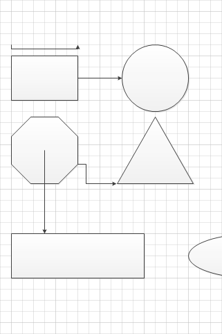
Here are three key observations after moving the three shapes:
The
connector between the upper rectangle and the circle has right angle
bends but is still attached at exactly the same two connection points.
This is an example of static glue, that is, glue that remains attached to a fixed point on a shape.
The
connector between the octagon and the long rectangle now contains a
right-angle bend. The tail of the arrow remains glued to the center
connection point, another example of static glue, but you now see
evidence of dynamic glue: the head of the arrow is still attached to the
long rectangle but it is connected at a different place along the edge
of the shape.
The
connector between the octagon and the triangle is glued dynamically at
both ends. Moving the triangle down caused the attachment point on the
triangle to change. In this particular case, the connection to the
octagon remained in the same place; however, a different set of shape
movements can cause the dynamic glue to the octagon to change locations
as well.
Note:
Save your changes to the Basic shapes drawing, and then close it.
By default, dynamic connectors
use right-angle bends as you saw in this exercise. You can change the
appearance of a dynamic connector by right-clicking it and selecting one
of three options: Right-Angle Connector, Straight Connector, or Curved
Connector.
As you move shapes that are
linked by dynamic connectors, Visio adjusts the connector segments. In
addition, as noted in the tip after Step 7, you can manually adjust
individual connector segments by dragging control handles. If at any
point, a dynamic connector has too many bends or becomes convoluted, you
can right-click it and then click Reset Connector. Visio redraws the
connector with the minimum number of bends and segments to fit in the
required space.
