Textures, Vertex Colors, and Fog
The basic effect also
handles rendering a texture. If the model you are loading from the
content pipeline includes textures, they are included as part of your
model and rendered automatically. If they aren’t included, you can
control that directly through the effect. To do this, add a new texture
variable:
To include a texture to load, add the file cat.jpg from your content project. Next, in your LoadContent method, switch the model you’re loading back to the box you used earlier.
Remove the lighting code you used for the emissive color example, and
create the texture and set it to the effect, as follows:
texture = Content.Load<Texture2D>("cat");
effect.TextureEnabled = true;
effect.Texture = texture;
Running the application shows you the box again, except this time you see each face of the box covered in the cat (see Figure 6).
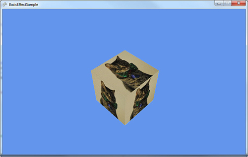
Notice that each face of the box looks the same. Because you’re using BasicEffect, you can use the other features as well. Add the standard lighting rig in your LoadContent method:
effect.EnableDefaultLighting();
The top of box is now slightly
lighter than the other two faces due to the lighting. If you had a
different model, you would see the specular highlights on it. You don’t
see them because you rendered a cube, which has only a small number of
vertices.
You’re almost done with the BasicEffect class. You can also use this effect for rendering vertex colors that are baked into the model. First, delete the code in your LoadContent method after the view and projection matrices are set, and add the following line:
effect.VertexColorEnabled = true;
This turns on the mode to
render with vertex colors enabled. If you run the application, you see a
black square-like blob. This is because the box model has no vertex
colors in it. Let’s modify the model to add vertex colors. Add a new vertex buffer variable that will hold the updated data:
Before you create the vertex
buffer to hold the updated data, define the structure for what kind of
data it will hold. The structure does not exist, so you need to create
it. Add the following lines to your project:
struct VertexColor : IVertexType
{
    public Vector3 Position;
    public Vector3 Normal;
    public Vector2 UV;
    public Color Color;
    public static readonly VertexDeclaration _decl = new VertexDeclaration(
        new VertexElement(0, VertexElementFormat.Vector3,
            VertexElementUsage.Position, 0),
        new VertexElement(12, VertexElementFormat.Vector3,
            VertexElementUsage.Normal, 0),
        new VertexElement(24, VertexElementFormat.Vector2,
            VertexElementUsage.TextureCoordinate, 0),
        new VertexElement(32, VertexElementFormat.Color,
            VertexElementUsage.Color, 0));
    public VertexColor(VertexPositionNormalTexture data)
    {
        Position = data.Position;
        Normal = data.Normal;
        UV = data.TextureCoordinate;
        Color = Color.White;
    }
    public VertexDeclaration VertexDeclaration
    {
        get { return _decl; }
    }
}
Whew, that’s a lot of information, so let’s break it down. First, notice that the structure expects to implement IVertexType. This is used to describe the data to the graphics device, and has only one method to get the VertexDeclaration.
Next, you have the actual data you want to store. The current box has
three pieces of data it stores: the position of each vertex, the normal
of each vertex, and the texture coordinates of each vertex. You keep
these three, but you also add the color.
Next, you create a static VertexDeclaration
(so you don’t create a new one every time you use the property that the
interface implementation requires). This is done by describing the data
this structure has in a language the graphics device understands. This
is done through an array of VertexElement, with each of the members in the array describing a piece of the data that will be held. Let’s look at the VertexElement constructor that’s used here.
The first parameter of the
constructor is the offset of the data (in bytes) from the beginning of
the vertex. For the first member, use zero; for the second member, use
12. This is because the first piece of data is a Vector3,
which contains three floats that are each four bytes large, and three
times four is 12. The others are calculated in the same manner. The
second parameter in the constructor is the format of the data. In your
first two members, your data is in the Vector3 format. Your third member is a Vector2, and the last is a Color. This parameter tells the graphics device how much data is required for each member.
The third parameter of the constructor is how the effects will use this data. In the first member, it is a Position, the second is a Normal, the third is a TextureCoordinate, and the last is a Color. You can ignore the last parameter for now—just use zero.
There is then a constructor on the structure itself taking in the data type of vertices in the model, VertexPositionNormalTexture,
which uses the old data. This constructor simply sets the default color
to white, and then uses the data from the passed in structure to fill
out the current structure.
This describes the new data,
so let’s take a look at creating the vertex buffer and filling it up
with good data. Add the following lines to the end of your LoadContent method:
int numberVertices = model.Meshes[0].MeshParts[0].NumVertices;
vb = new VertexBuffer(GraphicsDevice, typeof(VertexColor),
    numberVertices, BufferUsage.None);
VertexPositionNormalTexture[] data =
new VertexPositionNormalTexture[numberVertices];
VertexColor[] newData = new VertexColor[numberVertices];
model.Meshes[0].MeshParts[0].VertexBuffer.GetData <VertexPositionNormalTexture>(data);
// Copy the data
for (int i = 0; i < numberVertices; i++)
{
    newData[i] = new VertexColor(data[i]);
    newData[i].Color = Color.Red;
}
vb.SetData<VertexColor>(newData);
The box model you used has
exactly one mesh with one mesh part in it, so getting the total number
of vertices here is easy. You have to do a bit more work to make this
more generic, which is beyond the scope of this example. You can then
create your new vertex buffer using the type of structure you previously
defined that dictates what type of data you’re using.
Now you need to get the old data from the model. First, create two new arrays of vertices: one of the type VertexPositionNormalTexture, which is the type of data currently in the model, and the other of type VertexColor, the new data you use. Then, you can simply call the GetData method passing in the first array to have the model’s data push into
that array. You then can use the for loop to go through each of pieces
of old data, filling up the new data and setting the vertex color to
red. Finally, call SetData on your vertex buffer to fill it with the newly created data including the vertex color.
You’re not quite ready to render yet because your current DrawModel
call uses the model’s vertex buffer, not the one you just created. Add
the following method to draw with a specific vertex buffer:
private void DrawModelWithVertexBuffer(Model m, VertexBuffer v,
    Matrix world, BasicEffect be)
{
    foreach (ModelMesh mm in model.Meshes)
    {
        foreach (ModelMeshPart mmp in mm.MeshParts)
        {
            be.World = GetParentTransform(m, mm.ParentBone) * world;
            GraphicsDevice.SetVertexBuffer(v, 0);
            GraphicsDevice.Indices = mmp.IndexBuffer;
            be.CurrentTechnique.Passes[0].Apply();
            GraphicsDevice.DrawIndexedPrimitives(
                PrimitiveType.TriangleList, 0, 0,
                mmp.NumVertices, mmp.StartIndex, mmp.PrimitiveCount);
        }
    }
}
This is almost identical to the previous DrawModel call; it uses the passed in vertex buffer instead. Update your Draw method to call this instead of DrawModel,
and notice the black box is now a red box. However, just like
everything else, this effect can be combined with all the other effects.
For example, to see the box shaded by the standard lighting rig, add
the following line after your SetData call in LoadContent:
effect.EnableDefaultLighting();
You can texture this as well by adding the following code:
texture = Content.Load<Texture2D>("cat");
effect.Texture = texture;
effect.TextureEnabled = true;
Now, the box with the cat
picture has everything shaded red. If you change the previous vertex
color to blue, everything is shaded blue.
The last thing to talk about is the fog effect. Your project is a bit crowded, so to show this, replace your LoadContent method with the following lines:
protected override void LoadContent()
{
    spriteBatch = new SpriteBatch(GraphicsDevice);
    model = Content.Load<Model>("sphere");
    effect = new BasicEffect(GraphicsDevice);
    effect.Projection = Matrix.CreatePerspectiveFieldOfView(
       MathHelper.PiOver4, GraphicsDevice.Viewport.AspectRatio, 1.0f, 100.0f);
    effect.View = Matrix.CreateLookAt(
       new Vector3(0, 8, 22), Vector3.Zero, Vector3.Up);
    effect.EnableDefaultLighting();
    effect.SpecularColor = Vector3.Zero;
    effect.PreferPerPixelLighting = true;
    effect.FogColor = Color.Red.ToVector3();
    effect.FogEnabled = true;
    effect.FogStart = 10.0f;
    effect.FogEnd = 40.0f;
}
The
majority of the previous code should be old hat by now. You switched
back to the sphere to see the effect slightly better. You modified the
view matrix to be a little bit higher and quite a bit farther away, and
then turned on the standard lighting rig. Setting the specular color
back to black isn’t necessary, but it’s easier to see the effect without
the specular highlights.
Next, let’s set
the four fog parameters. Enabling the fog is pretty straightforward, as
is setting the color. The start and end parameters determine where the
fog effect starts and where it ends, although “end” is a bit of a
misnomer. These numbers are distances from the camera, where everything
closer than the start value has no fog effect, everything beyond the end
value has the full fog effect, and everything in between those values
scale linearly between no effect and full effect.
It is easier to visualize this by seeing it in action, so let’s update the Draw method to render some spheres. Delete everything from this method except the Clear call and add the following lines:
const int NumberSpheres = 55;
for (int i = 0; i < NumberSpheres; i++)
{
    Matrix world =Matrix.CreateTranslation(
        ((i % 5) - 2) * 4, 0, (i/5-3) * -4);
    DrawModel(model, world, effect);
}
This renders a set of
fifty-five spheres across the screen (you can change the constant to
lower/raise the amount you are rendering). The spheres start close to
the screen, and every set of five moves the next set a bit farther from
the camera. Eventually, as you get ten units away, the spheres start
having a red tint. The farther way they get from the camera, the moreof
the tint they get until they’re completely red (see Figure 7).
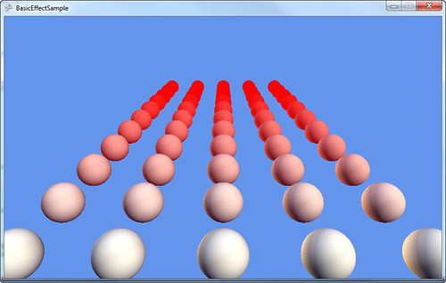
Fog adds another way to set the
final color of objects in the world. By using fog, you can make objects
appear to “disappear” the farther away they are. Using red doesn’t make
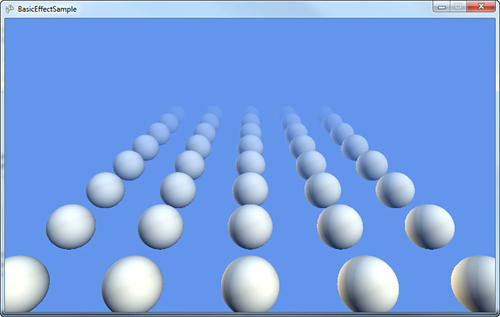
that apparent, but go back and change the FogColor in your LoadContent method to CornflowerBlue. Much like you see in Figure 8, the farthest spheres simply disappear, while the ones in the fog range appear to be faded.
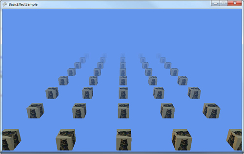
As before, all of these effects that BasicEffect uses can be combined with each other. To show this, switch your model back to the box, and add the following to the end of the LoadContent method:
texture = Content.Load<Texture2D>("cat");
effect.TextureEnabled = true;
effect.Texture = texture;
Notice your spheres are replaced with boxes that have pictures of cats on them, and they slowly fade out into the distance (see Figure 9).
As you can see, BasicEffect does quite a bit. Before moving on to the other built-in effects, let’s take a few minutes to see the interfaces it uses.
