The Pixels property
of WritableBitmap is
an array of int,
which means that each pixel is 32 bits wide. The Pixels property itself
is get-only so you can’t replace the actual array, but you can set and
get elements of that array.
A bitmap is a two
dimensional array of pixels; the Pixels
property of WriteableBitmap is a
one-dimensional array of int values.
The Pixels array
stores the pixels of the bitmap starting with the top row and working
down, and within each row from left to right. The number of elements in
the array is equal to the product of the bitmap’s pixel width and pixel
height.
If bm is a WriteableBitmap object,
then the number of elements in the Pixels
property is bm.PixelWidth * bm.PixelHeight.
Suppose you want to access the pixel in column x
(where x ranges from 0 through bm.PixelWidth – 1) and row y, where y
ranges from 0 to bm.PixelHeight – 1.
You index the Pixels property like so:
bm.Pixels[y * bm.PixelWidth + x]
Silverlight for Windows
Phone supports only one pixel format, sometimes denoted as PARGB32. Let
me decode this format code working backwards:
The “32” at the end means 32
bits, or 4 bytes. That’s the size of each pixel. The ARGB part indicates
that the Alpha byte (opacity) occupies the high 8 bits of the 32-bit
integer, followed by the Red byte, Green byte, and Blue byte, which
occupies the bottom 8 bits of the integer.
If A, R, G, and B are all of type byte, you can create a
32-bit integer pixel value like so:
int pixel = A << 24 | R << 16 | G << 8 | B
The shifted values—implicitly
converted to type int—are combined with the C# bitwise OR operator. You can
obtain the components of an existing pixel
value like so:
byte A = (byte)(pixel & 0xFF000000 >> 24);
byte R = (byte)(pixel & 0x00FF0000 >> 16);
byte G = (byte)(pixel & 0x0000FF00 >> 8);
byte B = (byte)(pixel & 0x000000FF);
When the Alpha channel byte is 255, the pixel is opaque. A value of 0
means completely transparent, and values in between indicate various
levels of transparency.
In the PARGB32 pixel format, the P stands for “premultiplied,” which
means that if the Alpha value is anything other than 255, then the Red,
Green, and Blue values have been already adjusted for the transparency
indicated by that Alpha value.
To better understand this
concept, let’s look at an example involving a single pixel. Suppose you
want the pixel to have the following color:
Color.FromArgb(128, 0, 0, 255)
That’s blue with 50%
transparency. When that pixel is rendered on a particular background
surface, the color of the pixel must be combined with the existing
colors of the surface. Drawn against a black background, the resultant
RGB color is (0, 0, 128), which is the average of the blue pixel and the
black background. Drawn against a white background, the resultant color
is (127, 127, 255). Each of the three components is an average of the
pixel and the surface.
With a transparency of
anything other than 50%, the resultant color is a weighted average of
the pixel source and the surface: The subscripts in the following
formulas indicate the “result” of rendering a partially transparent
“source” pixel on an existing “surface”:


When a bitmap is rendered on an
arbitrary surface, these calculations must be performed for each pixel.
Very often a single
bitmap is rendered on different surfaces multiple times. The
calculations shown above can be speeded up somewhat if the Red, Green,
and Blue components of the pixels in the bitmap have already been multiplied by the
Alpha channel. These pre-multiplied components are calculated like so:

and similarly for Green and
Blue. The resultant formulas for rendering the bitmap have half the
number of multiplications:

Whenever you’re working with the Pixels property of WriteableBitmap,
you’re dealing with pre-multiplied
alphas. For example, suppose you want a pixel in the bitmap to have an
RGB color value of (40, 60, 255) but with an Alpha value of 192. The
ARGB value in the bitmap would be (192, 30, 45, 192). Each of the R, G,
and B values have been multiplied by 192/255 or about 0.75.
In any pre-multiplied color value, the R, G, or B values should all
be less than or equal to the A value. Nothing will “blow up” if any R,
G, or B value is greater than A, but you won’t get the level of
transparency you want.
When working with ARGB
color values without pre-multiplied
alphas, there is a distinction between “transparent black,” the ARGB color (0, 0, 0, 0), and
“transparent white,” the ARGB color (0, 255, 255, 255). With pre-multiplied
alphas, the distinction disappears because transparent white is also (0,
0, 0, 0).
When you first create a WriteableBitmap, all the pixels are zero,
which you can think of as “transparent black” or “transparent white” or
“transparent chartreuse.”
By directly writing into the Pixels array of a WriteableBitmap you can create any type of image you can conceive.
Comparatively
simple algorithms let you create styles of brushes that are not
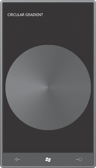
supported by the standard Brush derivatives. The content area of the CircularGradient
project consists solely of an Image
element waiting for a bitmap:
Example 1. Silverlight
Project: CircularGradient File: MainPage.xaml (excerpt)
<Grid x:Name="ContentPanel" Grid.Row="1" Margin="12,0,12,0">
    <Image Name="img"
           HorizontalAlignment="Center"
           VerticalAlignment="Center" />
</Grid>
|
The code-behind file for MainPage defines a rather arbitrary radius value and
makes a square WriteableBitmap twice
that value. The two for loops for x and y touch every pixel in that bitmap:
Example 2. Silverlight
Project: CircularGradient File: MainPage.xaml.cs (excerpt)
public partial class MainPage : PhoneApplicationPage
{
    const int RADIUS = 200;

    public MainPage()
    {
        InitializeComponent();

        WriteableBitmap writeableBitmap = new WriteableBitmap(2 * RADIUS, 2 * RADIUS);

        for (int y = 0; y < writeableBitmap.PixelWidth; y++)
            for (int x = 0; x < writeableBitmap.PixelHeight; x++)
            {
                if (Math.Sqrt(Math.Pow(x - RADIUS, 2) + Math.Pow(y - RADIUS, 2)) <
 RADIUS)
                {
                    double angle = Math.Atan2(y - RADIUS, x - RADIUS);
                    byte R = (byte)(255 * Math.Abs(angle) / Math.PI);
                    byte B = (byte)(255 - R);
                    int color = 255 << 24 | R << 16 | B;
                    writeableBitmap.Pixels[y * writeableBitmap.PixelWidth + x] =
 color;
                }
            }

        writeableBitmap.Invalidate();
        img.Source = writeableBitmap;
    }
}
|
The center of the WriteableBitmap
is the point (200, 200). The code within the nested for loops begins by
skipping every pixel that is more than 200 pixels in length from that center. Within the
square bitmap, only a circle will have non-transparent pixels.
If you connect that center point with any pixel in the bitmap, the line
makes an angle with the horizontal axis. The angle of that line is
obtained from the Math.Atan2 method. The method then assigns values to the R and B variables based on this angle, creates a color
value, and stores it in the Pixels array. A call to Invalidate then makes the actual bitmap image match
these pixels, and the bitmap is set to the Source
property of the Image element: