Understanding Packet Filters
Packet filters
are rules defined for a particular interface that allow or restrict
traffic by source address, destination address, direction, or protocol
type. You can think of packet filters as holes you create in a firewall
to allow external clients access to specific internal services. Without
packet filters, a firewall would simply block all requests originating
from the external network.
The packet filtering
feature in Routing And Remote Access is based on exceptions. You can set
packet filters per interface and configure them to do one of the
following:
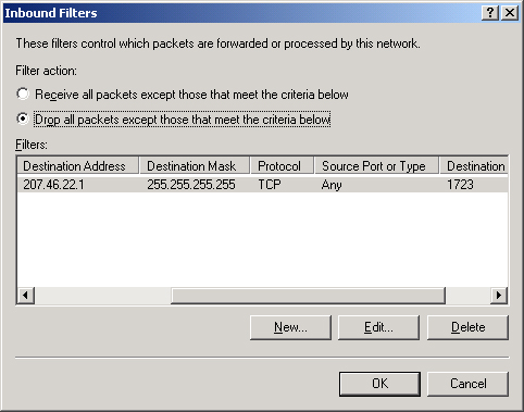
In Windows Server 2003, packet filters occur in two types: input filters and output filters. Input filters restrict traffic entering into an interface from the immediately attached network. Output filters restrict traffic being sent from an interface onto the immediately attached network. Figure 1 presents an example of an input filter denying all packets except those destined for TCP port 1723 and IP address 207.46.22.1.
Tip
Watch for questions in which all packet filters are defined correctly, but whose filter action is improperly configured. |
Creating Packet Filters
You create packet
filters in the Routing And Remote Access console through the IP Routing
node. Within the IP Routing node, select either the General node or the
NAT/ Basic Firewall node. Packet filters are then configured through the
properties dialog box of the appropriate interface, listed in the
details pane. Note that the NAT/Basic Firewall node allows you to create
packet filters only for external interfaces, whereas the General node
allows you to create packet filters for any interface.
To add a packet filter, complete the following steps:
1. | Open the Routing And Remote Access console.
|
2. | In the console tree, expand IP Routing, and click the General node.
|
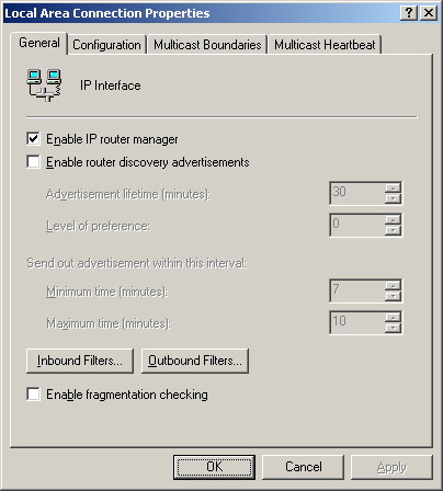
3. | In the details pane, right-click the interface on which you want to add a filter, and then click Properties.
The interface properties dialog box opens, shown in Figure 2.
|
4. | On the General tab, click either Inbound Filters or Outbound Filters.
|
5. | In the Inbound Filters dialog box or the Outbound Filters dialog box, click New.
|
6. | In the Add IP Filter dialog box, type the settings for the filter, and then click OK.
|
7. | In Filter Action, select the appropriate filter action, and then click OK.
|
Note
You can also define packet filters in a remote access policy profile. Remote access policies,
allow you to apply rules and restrictions to specific remote access
connections. By defining packet filters and the remote access policy
level, you can apply different levels of access restrictions to
different users. |
Basic Packet Filtering Scenario
In a basic
packet filtering scenario implemented on Windows Server 2003, two packet
filters are configured on an external interface. These packet filters
allow unsolicited connections to a Web server hosted on an internal
network. Such a scenario, in which a Web server is hosted at the address
207.46.22.1, is illustrated in Figure 3.
Packet filter #1 is
configured as an input filter and specifies a destination IP address of
207.46.22.1 with a mask of 255.255.255.255. This filter then specifies
the protocol TCP and associated Web service port of 80. Once the filter
is configured, the filter action in the Inbound Filters dialog box is
set to Drop All Packets Except Those That Meet The Criteria Below.
Packet
filter #2 is configured as an output filter and specifies a source IP
address of 207.46.22.1 with a mask of 255.255.255.255. This filter then
specifies the protocol TCP and associated Web service port of 80. Once
the filter is configured, the filter action in the Outbound Filters
dialog box is set to Drop All Packets Except Those That Meet The
Criteria Below.
Locked-Down Packet Filtering Scenario
In a
packet filtering implementation designed for locked-down security, four
filters are created for access to each service. As shown in Figure 9-40, one packet filter in this scenario is designed to match each of the four steps required for communication.
In
the case of an internal Web server, each packet filter indicates a
protocol of TCP, an associated port of 80, and the IP address of the Web
server (207.46.22.10) as either a source or destination, as
appropriate:
External interface, input filter: Destination address—207.46.22.10/32, Protocol-TCP port 80
Internal interface, output filter: Destination address—207.46.22.10/32, Protocol-TCP port 80
Internal interface, input filter: Source address—207.46.22.10/32, Protocol-TCP port 80
External interface, output filter: Source address—207.46.22.10/32, Protocol-TCP port 80
The set of packet filters is then configured to deny all other traffic.
Off the Record
On
the topic of packet filtering, exam reality definitely differs from
real-world reality. In real-world reality, most administrators use a
dedicated firewall product and simply define a single, bidirectional
filter on the external interface of that firewall to provide access to a
given internal service. But
that scenario would just be too simple for the MCSE exam. On the exam,
you’re likely to see a question on packet filtering in which each answer
choice lists a confusing array of four packet filters for each protocol
session. Typically, at least two of the answer choices specify the
correct port numbers, so it’s up to you to determine which answer choice
has correctly defined the filter directions on each interface. Such
questions aren’t easy, but if you can visualize the four steps in
communication required through the external and internal interfaces, you
should be in good shape. |
Advanced Packet Filtering Scenarios
Unlike Web servers,
many other services communicate over more than one channel.
Point-to-Point Tunneling Protocol (PPTP) traffic, for example, uses TCP
port 1723 to create and maintain a VPN connection and IP protocol 47 to
send data over that connection. To support remote users connecting
through PPTP to an internal VPN server, then, you must create one set of
packet filters for TCP port 1723 and another set for protocol number
47. Each set of packet filters follows the input and output pattern
shown in either Figure 3 or Figure 4.
Note
A
protocol number is typically used to define a stream of data associated
with a specific service. To create a packet filter for a protocol
number, in the Add IP Filter dialog box, select Other in the Protocol
drop-down list box. Then type the appropriate value in the Protocol
Number text box. |
Another protocol used
for VPN traffic, Layer2 Tunneling Protocol/Internet Protocol Security
(L2TP/IPSec), requires three sets of packet filters. This type of VPN
uses UDP ports 500 and 4500 to create and maintain the connection, and
IP protocol 50 to send data.
Tip
For the exam, know both the protocols numbers and ports required for PPTP and L2TP/IPSec. |
