Modem communications is one of those ideas that,
after you learn a bit of background, you wonder how on earth your system
actually pulls it off. I mean, you’re talking about tens of thousands
of bits per second busily bustling between two computers, all the while
negotiating compression routines, FIFO buffers, parallel-to-serial UART
conversions, modulations, and who knows what else. To combine all of
these complex technologies and achieve a remarkably high level of
accuracy is an amazing achievement. To help you appreciate some of the
hoops your computer, serial port, and modem have to jump through to
accomplish this wizardry, this section takes a closer look at just how
two modems communicate with each other.
Flow Control: The Communications Traffic Cop
Modem downloads come in
fast and furious, so what’s your computer supposed to do if it isn’t
ready to receive any data? Conversely, what if you’re sending data and
the remote system indicates that it can’t receive any more data just
now? How does your modem tell the CPU to stop processing data
temporarily?
These kinds of situations fall under the rubric of flow control,
which defines how the computer and the modem communicate with each
other to coordinate data exchanges and prevent overruns when one device
isn’t ready to receive information from the other. There are two types
of flow control: software and hardware.
Software Flow Control (XON/XOFF)
With software flow control,
the computer and modem send signals to each other that indicate whether
they’re ready to receive data. For example, suppose that you’re
downloading a file and the computer needs to pause the download briefly
while it attends to some other chores. To do this, it sends to the
remote system’s modem a special “hold your horses” signal called XOFF. (In data communications circles, X stands for transfer, so XOFF means transfer off.)
XOFF is an ASCII control code character (ASCII 19 or Ctrl+S) that gets
shipped out to the remote system just like any other character. When the
computer decides it’s okay to resume the download, it notifies the
remote system by sending a signal called XON
(which is another control code character: ASCII 17 or Ctrl+Q). Because
of these two signals, software flow control is also known as XON/XOFF flow control.
Note
If you find that a data
transfer has halted, it might be because your system has inadvertently
sent an XOFF flow control signal. Try pressing Ctrl+Q to send an XON
signal. If the remote system supports software flow control, this might
be enough to get the transfer going again.
Hardware Flow Control (RTS/CTS)
Because of
the high overhead associated with software flow control, it becomes
inefficient at data transfer rates higher than 2,400bps. For higher
speeds, hardware flow control
is a much better option. That’s because instead of firing an entire
character out to the remote device, hardware flow control just uses
individual serial port lines to send signals. Hardware flow control uses
two of these lines: RTS and CTS (which is why this method is also
called RTS/CTS flow control).
For example, suppose
that your modem wants to stop the computer from sending any more data
(because, for example, it has lost its Carrier Detect signal and so
doesn’t have a connection with the remote system). To do that, all it
does is turn off its CTS (Clear To Send) signal. The computer reads that
the serial port’s CTS wire is off, so it stops processing data for the
modem.
Similarly, the
processor’s willingness to accept more data from the modem is controlled
by the RTS (Request To Send) wire. If the processor turns off RTS, the
modem reads that the serial port’s RTS wire is off, so it pauses the
data transfer.
Data Bits: The Crux of the Matter
The role of the serial
port’s UART chip is to convert the eight parallel bits that PCs use to
represent data into a series of eight consecutive bits suitable for
squeezing through the serial port’s TD (Transmit Data) wire.
The problem, though, is
that not all computer systems use eight bits to represent their
characters. All PCs do, because they need the eight bits to represent
all 256 characters in the ASCII character set (because each bit can use
one of two states—on or off, 1 or 0—and 2 to the power of 8 is 256).
Most mainframe systems, however, use only seven bits to represent
characters because they recognize only the first 128 ASCII characters (2
to the power of 7 is 128). The number of bits used to represent a
character is called the data bits setting or the character length.
So, one of the most
important parameters when a remote system is involved is the number of
data bits it uses. Problems can arise, for example, if you send
eight-bit bytes to a system that knows how to deal with only seven of
them. In PC systems, fortunately, the first 128 ASCII characters have a 0
as their eighth bit, so it can be safely discarded during communication
with seven-bit systems.
Start and Stop Bits: Bookends for Your Data
The
data coursing through your computer is transferred from place to place
at extremely high speeds by using exquisitely timed procedures to
coordinate the transfers. This type of communications is called synchronous because it depends on timing signals.
The vagaries of modem communications, however, prevent such precise timing, so modems use asynchronous
communications. In asynchronous communications, as long as the remote
system is willing and able to receive data, the data is just sent out
whenever it’s ready to go.
But with no timing
involved, knowing where one character ends and the next begins becomes a
problem. You might think that you could just use the number of data
bits. For example, if your system and the remote system both use
eight-bit bytes, you could simply define every eighth bit as the
starting point for each character. Unfortunately, that approach would
work only in a perfect world that boasted noiseless telephone lines and
error-free data transfers. In the real world, in the journey between
here and there, legitimate bits can become missing, and extraneous
“bits” (that is, line noises) can get tossed into the mix.
To help the
receiving end delimit incoming characters, the sending system’s UART
tacks on extra bits on both sides of the data. At the front of the data,
the UART adds a start bit that defines the beginning of each character.
This is followed by the data bits, and then the UART appends a stop bit to mark the end of the character.
The start bit is
always the same, but different systems require different length stop
bits. Most systems use a single stop bit, but a few rare cases insist on
two stop bits. (You also read about systems that require 1 1/2 stop
bits. Half a
bit? It doesn’t make sense until you remember that these “bits” I’m
talking are really electromagnetic pulses traveling along an analog
carrier wave. Each pulse consumes a predefined amount of time—say,
1/14,400th of a second—so 1 1/2 bits is really just 1 1/2 pulses.)
At the receiving end,
the UART busies itself by stripping off the start and stop bits before
recombining the data bits into a full byte.
Parity: A Crude Error Check
The start and stop bits
can tell the receiving modem it has received corrupted data. For
example, if the modem is expecting eight data bits but gets seven or
nine, it knows that something has gone haywire, and it can ask that the
bit be retransmitted.
What if, however, a voltage spike or some line noise doesn’t add or subtract bits from a character, but instead changes
one of the existing bits? The receiving modem still gets the
appropriate number of data bits, so it won’t know that anything has gone
awry. To cover this kind of trouble, many systems that use seven-bit
characters also use parity checking. In this technique, an extra bit—called the parity bit—is
added to the data bits (but before the stop bit). The parity bit is set
to either 1 or 0, depending on the type of parity checking used:
| Even parity | In
this method, you first sum all the 1s in the data bits and see whether
you end up with an odd or even number. Your goal is to send out an even
number of 1s, so you use (or, technically, the UART uses) the extra
parity bit to ensure this. For example, suppose that the data bits are
0000111. The sum of the 1s here is 3, which is odd, so the parity bit
must be set to 1 to give you an even number of 1s. So, the UART sends
out 10000111. Similarly, suppose that your data bits are 1000001. The
sum of the 1s is 2, which is even, so the parity bit can be set to 0,
like so: 01000001. |
| Odd parity | This
is the opposite of even parity. Again, you first sum all the 1s in the
data bits and see whether you end up with an odd or even number. In this
case, however, your goal is to send out an odd number of 1s, and you
manipulate the parity bit accordingly. |
Most systems use even parity. (Two other kinds of parity—mark and space—exist, but these are virtually obsolete.)
How does this help
the receiving system check the data? Well, if it’s using even parity,
the receiving system’s UART checks the incoming bits and adds up all the
1s. If it finds an odd number of 1s, it knows that a bit was changed en
route, so it can ask for a retransmit. Of course, if a voltage spike
changes several bits, the number of 1s might remain even, so the
receiving UART wouldn’t detect an error. Therefore, parity is only a
crude error-checking mechanism.
Note
When setting up a
connection to a remote system, you need to make sure that the three
settings I’ve just talked about—data bits, stop bits, and parity—match
the parameters expected by the remote computer. If you’re not sure which
settings to use, note that two combinations are the most common: seven
data bits, even parity, one stop bit (usually written as 7-E-1); and
eight data bits, no parity, one stop bit (8-N-1). The former combination
is often used to connect to large online services that use mainframes
(such as CompuServe); the latter works for most bulletin board systems
and PC-to-PC connections.
Terminal Emulation: Fitting in with the Online World
When you use your modem
to connect to a remote computer, you are, essentially, operating that
computer from your keyboard and seeing the results onscreen. In other
words, your computer has become a terminal attached to the remote machine.
It’s likely, however,
that the remote computer is completely different from the one you’re
using. It could be a mainframe or a minicomputer, for example. In that
case, it isn’t likely that the codes produced by your keystrokes will
correspond exactly with the codes used by the remote computer.
Similarly, some of the return codes won’t make sense to your machine.
So, for your computer to act like a true terminal, some kind of
translation is needed between the two systems. This translation is
called terminal emulation because it forces your system to emulate the kind of terminal that the remote computer normally deals with.
Most communications programs
give you a choice of terminal emulation methods, such as ANSI for other
DOS/Windows computers, TTY for teletype terminals, or specific terminal
types, such as the DEC VT100 and VT52.
File Transfers: A Matter of Protocol
You’ll probably
spend most of your modem time on the Internet. However, you can also use
your modem to connect to other services, where you can chat with
others, access data, and also transfer files back and forth. When you
receive a file from a remote computer, it’s called downloading; when you send a file to a remote computer, it’s called uploading.
For your downloads and uploads to succeed, your system and the remote system must agree on which file transfer protocol
to use. The protocol governs various aspects of the file transfer
ritual, including starting and stopping, the size of the data packets
being sent (in general, the larger the packet, the faster the transfer),
how errors are handled, and so on. Many different file transfer
protocols are available, but as you’ll see later, Windows XP supports
the following seven:
| Xmodem | Designed
in 1977, this was the first protocol for PCs. Because it uses only a
simple error-checking routine and sends data in small, 128-byte packets,
Xmodem should be used only as a last resort. |
| 1K Xmodem | This is an updated version of Xmodem that uses 1024-byte data packets and an improved 16-bit cyclic redundancy check
(CRC) error-checking protocol. This makes 1K Xmodem more reliable than
plain Xmodem and, as long as the telephone lines are relatively
noise-free, much faster as well. |
| Kermit | This
is a flexible protocol that can handle the seven-bit bytes used by
mainframes and minicomputers. It’s very slow, however, and you should
avoid it if the remote machine supports any other protocol. |
| Ymodem | This
protocol provides all the benefits of 1K Xmodem (including 1024-byte
packets and CRC error control) but also implements multiple-file
transfers and the exchange of file data, including the name and size of
each file. |
| Ymodem-G | This
protocol is the same as Ymodem, except that it performs no error
checking. Instead, it relies on the built-in error checking of modern
modems (such as V.42 and MNP 4). |
| Zmodem | This
is the fastest of the file transfer protocols and the most reliable.
Zmodem doesn’t use a fixed packet size. Instead, it adjusts the size of
each packet based on the line conditions. For error checking, Zmodem
uses a 32-bit CRC for enhanced reliability. Zmodem is, by far, the
choice among online aficionados. |
| Zmodem with Crash Recovery | This
version of the Zmodem protocol offers crash protection. This means that
if the file transfer bails out before completing, you can restart and
the Zmodem protocol resumes the transfer where it left off. |
Configuring Serial Ports
As you’ve seen so far,
serial ports play a vital role in modem communications. To make sure
that your serial ports are ready to do their duty, you might want to set
a few properties. Here’s how it’s done:
1. | Double-click Control Panel’s System icon to display the System Properties dialog box.
|
2. | In the Hardware tab, click Device Manager.
|
3. | Open the Ports (COM and LPT) branch.
|
4. | Double-click the COM port you want to work with. The COM port’s property sheet appears.
|
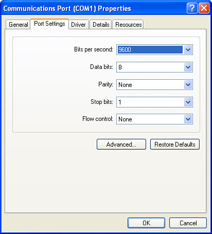
5. | Display the Port Settings tab, shown in Figure 1.
These drop-down lists set up default communications settings for the
port. You don’t need to adjust these values for your modem’s port,
however, because the settings you specify for the modem will override
the ones you see here. You need to change these values only if you’ll be
attaching some other kind of device to the port.
|
6. | Click Advanced to display the Advanced Settings dialog box.
|
7. | Make
sure that the Use FIFO Buffers check box is activated, and make sure
the UART’s Receive Buffer and Transmit Buffer sliders are all the way to
the right (High).
|
8. | Click OK to return to the COM port’s property sheet.
|
9. | Click OK and, if necessary, restart your computer.
|
