Parents and teachers often admonish children by
saying, “Neatness counts!” Although children tire of hearing that
phrase, neatness is an important factor when you create Visio drawings.
It is remarkable how much more effective your diagram can be if the
viewer isn’t distracted by lines that cross unnecessarily or shapes that
are almost, but not quite, aligned.
|
When you drop shapes onto a
Visio drawing page, their horizontal (X-axis) and vertical (Y-axis)
positions are obvious. Less obvious is each shape’s position on the
Z-axis. You see evidence of the placement on the Z-axis when you drop
shapes on top of each other, because some shapes appear to be “in front
of” or “behind” other shapes.
Even when shapes are not on top of each other, however, Visio keeps track of the Z-order,
that is, the position of each shape along the Z-axis. The first shape
you drop on a page is at the back, and every subsequent shape you add is
one step in front of the previous one. If you’re in doubt, try the
following experiment:
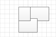
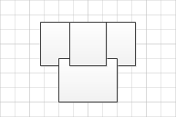
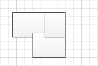
Drop three shapes in separate parts of the drawing page so none of the shapes are touching. Drag the second shape you dropped so it partially overlaps the third. Notice that it appears behind the third shape. Drag
the first one so it overlaps part of the second and part of the third.
The first shape will maintain its Z-order and appear behind the other
two.
You can alter the Z-order of any
shape or shapes by using the Bring Forward or Send Backward buttons in
the Arrange group on the Home tab. You can also right-click a shape and
select Bring To Front or Send To Back from the context menu.
Tip:
The buttons on the Home tab
default to moving a shape one step forward or backward, but you can use
commands on each button’s menu to move the full distance in either
direction. The right-click context menus have the opposite default: they
move the shape(s) the full distance in one direction, but they contain
drop-down menus to move one step at a time.
|
In
this exercise, you will work with several valuable Visio tools that
align and distribute shapes on the drawing page. After creating a
collection of randomly placed shapes, you will rearrange them into neat
rows and columns without dragging a single shape.
Note:
Start Visio, or if it’s already running, click the File tab and then
click New. In the Template Categories section, click Flowchart, and then
double-click the Basic Flowchart thumbnail. Save the new drawing as Align and Space BEFORE.
Drag four Process
shapes into a row but deliberately space them very irregularly and
don’t align them with each other. Repeat with four additional shapes in a
second row. Finally, drag the resize handles so some shapes are wider
than others.
Tip:
Your diagram doesn’t need
to look exactly like the one shown here, but this is an example of the
type of “messy diagram” you should create.
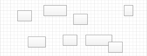
Your first task is to rearrange the shapes in the upper row so they are vertically aligned. Draw a bounding box around the shapes in the top row.

Warning:
Important
The leftmost shape in the
previous graphic has a bolder selection outline than the others. This is
the shape Visio will use as the anchor shape
for the operations you will perform in this exercise. Just as its name
suggests, the anchor will stay in place—the other shapes will move
relative to it.
It’s important to notice which
shape is the anchor because the results can be very different with
different anchor shapes. For that reason, it’s also important to
understand how Visio selects the anchor shape so you can change it if
you want to:
If you use a
bounding box or another technique to select multiple shapes at once, the
anchor will be the shape that is farthest to the back. This will
usually be the shape that you placed on the page first unless you have
changed the Z-order by using the Send Backward or Send Forward
functions. You
can override the Z-order by manually selecting multiple shapes: hold
down the Shift key and click on a series of shapes. The anchor shape
will be the first shape you select.
Position

On the Home tab, in the Arrange group, click the Position
button, and then move the cursor over a series of entries on the menu
to observe the Live Preview results. For example, point to Align Left, Align Center, and then Align Right to see shapes aligned along their left edges, centers, or right edges.
When you point to either Auto Align or Align Middle, you see the desired outcome, so click either entry.

Tip:
If you want to prove to
yourself that your choice of anchor shape does make a difference, try
this experiment: Undo the alignment action so the shapes in the top row
are back where they started; click any shape so it will be the anchor;
hold down Shift and click the remaining shapes in the row; align the
shapes. You’ll see that the row has been aligned to your chosen anchor.
Repeat Step 3 with the second row, using Align Middle.

Now that the alignment looks better, you can correct the irregular spacing between shapes. Select all of the shapes in the top row. Then on the Home tab, in the Arrange group, click the Position button. In the Space Shapes section of the menu, point to Auto Space
and note that Visio leaves the anchor shape in place and arranges the
remaining shapes so the distance between the edges of each pair of
shapes is identical.
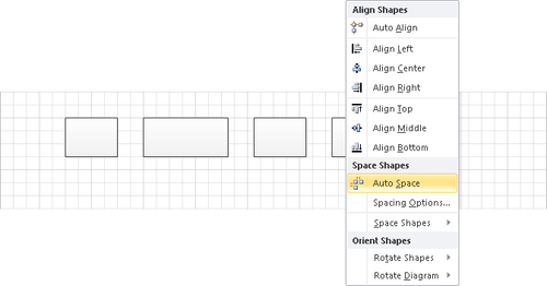
Although Auto Space can be useful, point to Space Shapes in the Space Shapes section to see other options. Then click Distribute Horizontally. Whereas
Auto Space leaves only the anchor in place and sets equal spacing
between pairs of shapes, Distribute Horizontally leaves the two
outermost shapes in place prior to adjusting the inter-shape spacing.

Select the leftmost shape in the top row. Then hold down Shift and click the leftmost shape in the bottom row. On the Home tab, in the Arrange group, click the Position button, and then click Align Center. Hold down Shift and click the next shape to the right in each row, and then repeat Step 8. Use the same technique to align the third and fourth pair of shapes in each row.
Note:
In Visio you can press F4 to
repeat the previous operation. For example, after clicking Align Center
in Step 8, you can complete Steps 9 and 10 by selecting a pair of
shapes and then pressing F4 to align them.

Note:
Save your modified drawing as Align and Space AFTER.
In
this exercise, you aligned and spaced the shapes on the page by using
one particular combination of options. You may find it worthwhile to
experiment with other combinations so you understand the full range of
choices provided by Visio.
|