Although XNA Game Studio 4.0 provides five built-in
effects to use in your game, you are not limited to just these five for
your Windows and Xbox 360 games. Underneath the five built-in effects
are compiled effects graphics programs that implement the features that
are exposed by the different types.
What Is a Custom Effect?
Custom effects enable you to
write an effect file that contains the vertex and pixel shaders that
determine how the geometry you draw is transformed and shaded before
being outputted to the screen. This gives you tremendous control over
how geometry is rendered in your game. With this control also comes some
additional difficulty in programming and debugging your graphics code.
Although custom effects work in both the Reach and HiDef profiles, custom effects are not supported on Windows Phone 7.
High Level Shading Language
Effect
files in XNA Game Studio are written in the High Level Shading Language
or HLSL for short. HLSL was created by Microsoft for use by
applications written using Direct3D. The underlying XNA graphics stack
is built on Direct3D and thus uses HLSL as the effect shading language.
The syntax of HLSL is similar to C but with additional language support specifically designed for graphics operations.
HLSL supports many of the common keywords found in C such as bool, int, if, and else but also have specific keywords such as sampler, technique, and pixelshader.
HLSL also supports built-in intrinsic functions that are used in many graphics algorithms. For example, the dot(a, b) intrinsic returns the dot product scalar value between two vectors a and b.
HLSL has multiple versions,
which can differ from the number of compiled instructions that can be
used, the number of textures that can be accessed, to the actual
keywords and intrinsic functions that are available. These versions are
called shader models and can differ from the vertex to the pixel
shaders. If your game is targeting the Reach profile, you can use the
2.0 shader model version. The HiDef profile supports shader model 3.0+.
Note
The Xbox 360 supports a
special shader model version of 3.0, which includes instructions that
are not available on other platforms such as vfetch. The list of available instructions can be found in the XNA Game Studio documentation.
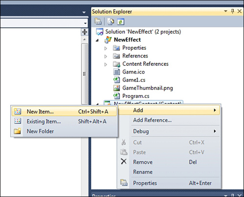
Let’s start with a new
effect file. Effect files generally end with the .fx extension. Create a
new XNA Game Studio Windows project. Then right-click the content
project and select Add -> New Item (see Figure 1).
The Add New Item dialog
displays a few of the different content types supported by XNA Game
Studio. Select the Effect File listing and name it CustomEffect.fx. Finally, click the Add button (see Figure 2).

The CustomEffect.fx
file is not added to your content project. Effect files are built using
the content pipeline using the Effect importer and processor. Because
effect files contain code that is run on the graphics processor, the
code needs to be compiled into a binary format suitable to run on the
graphics hardware. This is similar to how a C
application must be compiled to run on your Windows PC. The content
pipeline compiles your effect file and reports build errors. Just like
your game code, the effect file can contain syntax errors that are
reported in the build output window in Visual Studio.
Parts of an Effect File
Double-click the newly
created CustomEffect.fx file to view the contents of the file in the
Visual Studio editor. Notice that the newly created file is not empty.
The file is filled with the default effect file template to help you get
started writing your effect.
Global Variables
The first part of the effect template declares three global variables that can be used from within the shaders you write.
float4x4 World;
float4x4 View;
float4x4 Projection;

// TODO: add effect parameters here.
The World, View, and Projection matrices are used to transform the geometry from local space into screen space . Notice that the variable type is not matrix, but is instead float4x4
(pronounced float four by four). This is essentially a four-by-four
array of floats, which can be used to represent a 4×4 matrix. The TODO
comment lets you know that this is the location where you can add new
global parameters to the effect file.
Vertex Structures
The next section of the template defies two structures.
struct VertexShaderInput
{
    float4 Position : POSITION0;

    // TODO: add input channels such as texture
    // coordinates and vertex colors here.
};

struct VertexShaderOutput
{
    float4 Position : POSITION0;

    // TODO: add vertex shader outputs such as colors and texture
    // coordinates here. These values will automatically be interpolated
    // over the triangle, and provided as input to your pixel shader.
};
Input Vertex Structure
The first structure VertexShaderInput
defines how the geometry will be passed into the shader. In this case,
only the position of the geometry is passed into the shader with the
name Position and has a type of float4. Notice that to the right of the variable is POSITION0. This is an input semantic that defines what each field represents in the vertex. It is used to define which portions of the input vertex stream correspond to the fields of the vertex structure in the shader.
When geometry is drawn in a game, a VertexDeclaration
must be specified in order for the graphics hardware to determine how
each field in a vertex element is used. The graphics hardware can then
pass each of the vertices into the vertex shader.
The type used by the vertex
in your game and the type used in the shader don’t have to match. The
graphics card tries to map the vertex data the best it can given the
hints from the semantics. For example, your VertexBuffer might contain the positions as Vector3 values, which contains three floats, but your input vertex structure might be expecting a float4. The first three components will be copied into the input vertex structure and the final w component will be left blank.
Output Vertex Structure
The output vertex
structure is used to define what values are passed out of the vertex
shader and into the pixel shader. Although the vertex shader is run for
each geometry vertex that is drawn, the pixel shader is run for each
pixel that makes up the triangle that is drawn.
The output vertex structure is
often used as the input structure for the pixel shader, but this is not
required. What is required is for the vertex shader to output a
position. The position is required because it is used to determine how
the triangle should be displayed on the screen. If portions or all of
the triangle corners are not going to be displayed on the screen, then
the pixel shader is not drawn for these pixels.
You might already notice
something of importance. Although the vertex shader is run exactly once
per vertex, the pixel shader can be run from 0 to the total number of
pixels on the screen for each triangle. So there is no one-to-one
relationship between the vertex and pixel shaders. How does the output
from the vertex shader correspond to the input of the pixel shader when
it can be run many more times than the vertex shader?
The answer is that the
values from the vertex shader do not directly pass into the pixel
shader. The values first pass through an interpolater. The interpolater
does exactly what its name describes, which is to interpolate values
across the face and edges of the triangle.
After the vertices of the
triangle are passed through the vertex shader, the pixels that make up
the triangle are determined and the pixel shader is run for each of the
pixels. The interpolator is used to determine the values between each
vertex. For example, if one vertex has and X position of 0.1 and another
has an X position of 0.5, then the pixel that is halfway between the
two on the edge of the triangle has an X value of 0.3.
Along with the position
values, other values can be interpolated across the triangle such as
color if the vertices or texture coordinates.
Vertex Shader
The next section of the effect template defines the vertex shader.
VertexShaderOutput VertexShaderFunction(VertexShaderInput input)
{
    VertexShaderOutput output;
    float4 worldPosition = mul(input.Position, World);
    float4 viewPosition = mul(worldPosition, View);
    output.Position = mul(viewPosition, Projection);

    // TODO: add your vertex shader code here.

    return output;
}
This is a very simple vertex shader. A new instance of the VertexShaderOutput
structure is defined and used to return the final position at the end
of the shader. The vertex shader then takes the input position and
multiples it by the World matrix first to move the position into world space. It then multiplies the position by the ViewProjection to move the it into projection or clip space. to move the position into view space. Finally, it multiplies the position by the
Pixel Shader
The output position from
the vertex shader determines all of the pixels that are displayed on
the screen. The pixel shader is then run for each of the pixels.
The following simple pixel shader is defined by the new effect template.
float4 PixelShaderFunction(VertexShaderOutput input) : COLOR0
{
    // TODO: add your pixel shader code here.

    return float4(1, 0, 0, 1);
}
Notice that the input to the pixel shader function takes an argument of the type VertexShaderOutput. Also notice that the output of the pixel shader is a float4 that represents the color to write to the color buffer. The COLOR0 semantic is used to tell the graphics hardware the pixel shader plans to output the color using the float4 return value of the shader.
This simple shader outputs a solid color of red. A float4 color is storage in RGBA format. This means that the X component of the float4 is the red channel. The green, blue, and alpha values are stored in the Y, Z, and W components respectively.
Techniques and Passes
The last section of the effect template defines the techniques and the passes they contain.
technique Technique1
{
    pass Pass1
    {
        // TODO: set renderstates here.
        VertexShader = compile vs_2_0 VertexShaderFunction();
        PixelShader = compile ps_2_0 PixelShaderFunction();
    }
}
A
technique is a collection of passes that are designed to run for each
triangle. An effect file must contain at least one technique, but it can
contain many techniques. Multiple techniques can be used when you need
to alter which vertex and pixel shaders to use for particular geometry.
For example, multiple techniques are used in the five built-in effects
to handle the different types of input vertices that are drawn using the
effects.
An effect pass defines which vertex and pixel shader should be used by the graphics hardware. The shader version along with the compile
keyword determine how the vertex and pixel shaders should be compiled.
The default template uses shader model 2 as the default, so vs_2_0 is used for the vertex shader and ps_2_0 is used for the pixel shader.
Each effect pass can also contain a set of render state to set before drawing geometry.
This brings you to the end of
the new effect file template. It is not too complex, but this program
runs many times very quickly on the graphics hardware. The complexity of
your effects has a direct influence on the performance of drawing
geometry using your effect. Some operations are more expensive than
others, but a general tip is to keep the number of operations to a
minimum.
