Texturing
To give the triangles a little
more detail, you are going to remove the color from the triangles and
replace them with a texture to map across each of the two triangles.
Textures are mapped to triangles using texture coordinates. Each vertex
gets a specific texture coordinate to tell the graphics hardware that at
this vertex, the following coordinate should be used to sample from the
texture. No matter the pixel size of a texture, the texture coordinates
are from 0 to 1 in both width direction called U and the height direction called V. Position 0,0 or the origin of the texture is the top left of the texture, and position 1,1 is the bottom right of the texture.
Note
Volume textures have an additional axis for depth, which uses the W component.
Next, you update the
existing sample to use a texture instead of vertex colors. Add any
texture to your content project. For example, add Fractal.png.
Note
Constraints are placed on textures depending on the GraphicsProfile that you have specified for your game. The HiDef profile can support texture sizes up to 4096, and textures in the Reach profile must be 2048 or smaller in size. In addition, Reach textures don’t support the wrapping, mipmaps, or DXT compression if the texture is not a power of two.
In your game, change the vertex
type used to store the vertices and declare a member variable to store
the texture you plan to render on the quad.
VertexPositionTexture[] userPrimitives;
Texture2D colorTexture;
You have removed the VertexPositionColor type and replaced it with the VertexPositionTexture. This vertex type includes a field to use for the texture coordinate.
In the game’s LoadContent method, load the texture and set the texture onto the device.
// Load the texture we want to display
colorTexture = Content.Load<Texture2D>("Fractal");
GraphicsDevice.SamplerStates[0] = SamplerState.LinearClamp;
GraphicsDevice.Textures[0] = colorTexture;
You have seen the first line previously. Load the texture like normal through the content pipeline and store it in a Texture2D variable instance.
Then, set a SamplerState for the first texture sampler on the GraphicsDevice. As discussed in this article, the SamplerState
tells the graphics hardware how to sample the texture as it textures
any triangles. The final line of code sets the texture the GraphicsDevice should sample from when drawing.
Because you are now using a new
vertex type, update how you declare the array of vertices for the quad
you are drawing. Remove the existing list of vertices in the LoadContent method and add the following lines of code:
// Create the verticies for our triangle
userPrimitives = new VertexPositionTexture[4];
userPrimitives[0] = new VertexPositionTexture();
userPrimitives[0].Position = new Vector3(-1, 1, 0);
userPrimitives[0].TextureCoordinate = new Vector2(0, 0);
userPrimitives[1] = new VertexPositionTexture();
userPrimitives[1].Position = new Vector3(1, 1, 0);
userPrimitives[1].TextureCoordinate = new Vector2(1, 0);
userPrimitives[2] = new VertexPositionTexture();
userPrimitives[2].Position = new Vector3(-1, -1, 0);
userPrimitives[2].TextureCoordinate = new Vector2(0, 1);
userPrimitives[3] = new VertexPositionTexture();
userPrimitives[3].Position = new Vector3(1, -1, 0);
userPrimitives[3].TextureCoordinate = new Vector2(1, 1);
Instead of having to declare a color for each vertex, you are now specifying a TextureCoordinate for each vertex.
Note
Although
you are defining the texture coordinates in code explicitly, this is
mostly done within a 3D content creation package when an artist is
creating the models for your game.
The final changes to the code
need to occur in your custom shader. Add a new global variable for the
texture sampler you will use in the shader. Add the following global
variable to your custom shader effect file.
sampler ColorTextureSampler : register(s0);
Sampler is a
special type defined in the HLSL language. It lets the compiler know
that the variable is used as a texture sampler. The register definition
at the end is not required but does enable you to specify which of the
samplers the variable will map to. In general, the sampler variables map
to the order they are declared. Explicitly defining which sampler to
use enables you more control if you are using multiple textures and want
to specify textures to map to specific samplers.
The vertex shader input and output structures need to be updated to include the texture coordinate to use per vertex.
struct VertexShaderInput
{
    float4 Position : POSITION0;
    float2 TexCoord : TEXCOORD0;
};

struct VertexShaderOutput
{
    float4 Position : POSITION0;
    float2 TexCoord : TEXCOORD0;
};
The TexCoord field is passed in as part of the vertices that you defined in your quad. Notice that the TEXCOORD0
semantic is used. Vertices can contain multiple texture coordinates,
and this specifies that this field should be the first one defined in
the VertexDeclaration.
The vertex shader then needs to copy this value directly to the VertexShaderOutput. Add the following line to your vertex shader:
output.TexCoord = input.TexCoord;
The final step is to
update the pixel shader to read the final color from the texture sampler
and to output the color. Replace your pixel shader with the following:
float4 Color = tex2D(ColorTextureSampler, input.TexCoord);
return Color;
Use the tex2D
intrinsic function to return the color from the texture sampler. The
input texture coordinate are interpolated across the face of the
triangle using the rules setup in the SamplerState.
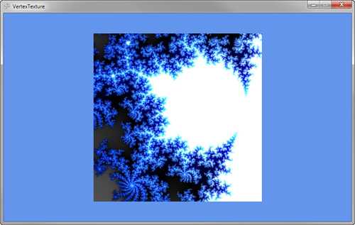
Running the sample code now should display a quad with the fractal texture and looks like Figure 2.
Setting Sampler States in Effect File
The preceding code used the XNA
Framework APIs to set the sampler state and texture to use when running
the effect. It is also possible to set this directly in the effect file
itself so it does not require code changes within your project.
Note
Be mindful when setting
states within the effect file. These changes can affect how other draw
calls are rendered, so be watchful of which states you change.
To set the sampler state in the effect file, update the file with the following global texture and sampler:
texture ColorTexture;
sampler ColorTextureSampler : register(s0) = sampler_state
{
   Texture = (ColorTexture);
   MinFilter = Linear;
   MagFilter = Linear;
   MipFilter = Linear;
   AddressU  = Wrap;
   AddressV  = Wrap;
};
You have added a new variable to hold the texture to use. The ColorTextureSampler has been updated to specify the sampler settings to use.
Because you added the new ColorTexture effect variable, you also need to set this in your game. In your game’s LoadContent method, add the following line of code after you load the effect:
customEffect.Parameters["ColorTexture"].SetValue(colorTexture);
Instead of setting the texture on the GraphicsDevice,
pass which texture to use directly to the effect file. When using
sample states directly in the effect file, these settings take affect
after you call Apply on the EffectPass that is using them.
Running the sample now should look just like before. Let’s change that by showing off some of the sampler states.
Textures Repeating
In the previous
examples, the texture coordinates ranged from 0 to 1, but you are not
limited to just using these values. At times, it is useful for textures
to repeat over and over across triangles. For example, you might make a
sports game that has a large grass field. Creating a large texture that
covers the whole field can be a large memory expense. An option is to
have a smaller texture that repeats itself over the field every few
feet. The higher number used for the texture coordinates, the more
number of times the texture repeats.
There are two ways for
the texture to repeat itself. The first is called wrapping, which causes
the texture to just start over at the end of the first texture. The
second is called mirroring, which causes the texture to reverse each
time it is repeated.
To see some examples of texture, update the vertices deceleration.
// Create the verticies for our triangle
userPrimitives = new VertexPositionTexture[4];
userPrimitives[0] = new VertexPositionTexture();
userPrimitives[0].Position = new Vector3(-1, 1, 0);
userPrimitives[0].TextureCoordinate = new Vector2(0, 0);
userPrimitives[1] = new VertexPositionTexture();
userPrimitives[1].Position = new Vector3(1, 1, 0);
userPrimitives[1].TextureCoordinate = new Vector2(2, 0);
userPrimitives[2] = new VertexPositionTexture();
userPrimitives[2].Position = new Vector3(-1, -1, 0);
userPrimitives[2].TextureCoordinate = new Vector2(0, 3);
userPrimitives[3] = new VertexPositionTexture();
userPrimitives[3].Position = new Vector3(1, -1, 0);
userPrimitives[3].TextureCoordinate = new Vector2(2, 3);
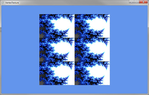
The important changes are the TextureCoordinate values. Originally, the coordinates were set between 0 and 1 for both the U and V coordinates. You updated the code to set the max U value to 2 and the max V value to 3. This causes the resulting image to repeat two times from left to right and three from top to bottom.
Running the code now produces results similar to Figure 3. Notice that the texture wraps two times from left to right and three times from top to bottom.
The texture sampler uses
wrapping because you set that in the effect file. If you update the
sampler to use mirroring, you see different results.
Update the sampler in the effect file to use the following code:
sampler ColorTextureSampler : register(s0) = sampler_state
{
   Texture = (ColorTexture);
   MinFilter = Linear;
   MagFilter = Linear;
   MipFilter = Linear;
   AddressU  = Mirror;
   AddressV  = Mirror;
};
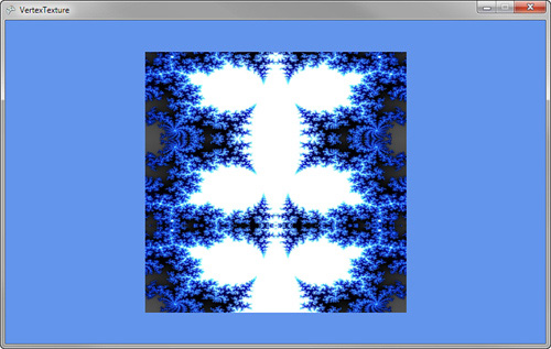
You changed both the AddressU and AddressV modes to Mirror. The texture now displays in reverse on every other repeat of the texture.
Running the code now produces a mirroring effect and looks like Figure 4.