Application Model Layering System
Application model
layering is the architectural principle in Dynamics AX that allows
granular customizations and extensions to model element definitions and
hence the structure and behavior of applications. When a version of
Dynamics AX is released that is not specific to any country/region, all
model elements that define the application reside in the lowest layer of
an element layering stack. The Dynamics AX runtime environment,
however, uses more than these element definitions when it instantiates
application objects—it assembles an element definition from model
elements at all levels of the element layering stack. Elements defined
at higher levels of the element layering stack override elements defined
at lower levels of the stack. The object that the runtime environment
eventually instantiates is thus an instance of a dynamic type definition
composed of model elements at multiple layers of the element layering
stack.
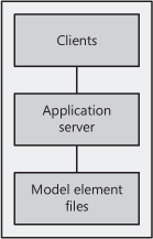
Figure 1
illustrates the components in the application model layering system.
Model elements are stored in a separate file on each layer whenever they
are saved from MorphX. Element definitions are read from these files
and dynamically composed by the Dynamics AX runtime environment. Object
instances are created on either the server or the client, based on the
model element definition. The client can be the MorphX development
environment, the rich client, or the .NET Business Connector client.

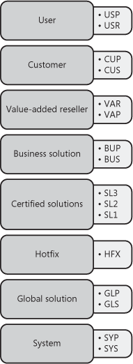
Figure 2 shows the element layers in the application model layering system.

Table 1 contains a description of each element layer, including ID ranges.
Table 1. Layer Descriptions
| Layer | Description | ID Range |
|---|
| USP
USR | User
Individual companies or companies within an enterprise can use this layer to customize unique customer installations. | 50001–60000 |
| CUP
CUS | Customer
Companies and business partners can modify their installations and add company-specific modifications to this layer.
This layer is included to support the need for in-house
development without jeopardizing modifications made by business
partners. | 40001–50000 |
| VAP
VAR | Value-added reseller
Business partners use this layer, which has no business restrictions, to add any development done for their customers. | 30001–40000 |
| BUP
BUS | Business solution
Business partners develop and distribute vertical and horizontal solutions to other partners and customers. | 20001–30000 |
| SL3
SL2
SL1 | Certified solutions
Partners certified under the Microsoft Dynamics Industry
Solution program distribute their solutions in the SL layers. | 1–20000 |
| HFX | Hotfix
The Dynamics AX Sustained Engineering team delivers critical hotfixes using the HFX layer. | 1–20000 |
| GLP
GLS | Global solutions
The Dynamics AX Global Development and Localization team
provides a set of GLS layers that contain country/region-specific
functionality. | 1–20000 |
| SYP
SYS | System
This is the lowest model element layer and the location of the
standard Dynamics AX application. Only Microsoft has access to the
element definitions at this layer. | 1–20000 |
Working with the Layers
As you see in Figure 2,
the lowest layer is the system layer, and the highest is the user
layer. You use the client configuration utility to specify the layer at
which you want to customize and extend the Dynamics AX application. When
the MorphX environment is launched, it adds or modifies elements at
this layer, the working layer, of the model layering system. It cannot,
however, modify or delete a model element defined at a higher model
layer.
Note
The
Dynamics AX runtime environment always composes model elements starting
with the user layer, regardless of the layer in which you are working. |
When you modify a
model element at a layer lower than the working layer, the element is
copied to the working model element layer. A class header or method
element, for example, is copied to the working layer when it is
modified. A table header, field, field group, index, or method element
is copied to the working layer when modified. An entire form or report
element is copied if any of its members are modified. For example, if
you add a button to a form, the entire form is copied to the current
layer. If you delete the model element from the working layer, the model
element at a lower layer is used instead. In this way, you can undo
modifications and easily return to the original model element
definitions. You can also compare objects from two different layers by
using the MorphX Compare tool.
As shown in Figure 2
all model element layers (except HFX and SL1 through SL3) have an
associated patch layer. Patch layers handle patches, minor updates,
service packs, and hotfixes. Logically, a patch layer is placed directly
above the layer that it is patching. A patch layer’s name contains the
first two characters of the element layer’s name and then the letter P.
For example, the first three patch layers are named SYP, GLP, and BUP.
As a best practice, you should move the content of the patch layer into
the main layer with each release of the application.
The solution layers (SL1,
SL2, and SL3) are new in Dynamics AX 2009. They are intended for
Microsoft certified solutions. Any of these solutions can be installed
in the SL1, SL2, SL3, BUS, or BUP layer. Prior to installation, rename
the layer file to match the desired layer. These solution layers enable
customers to use up to five certified solutions simultaneously.
Model Element IDs
Most model elements have a
unique identifier (ID) that is represented as an unsigned 16-bit
integer. To avoid conflict, each layer has a range of available IDs, as
listed in Table 1.
The lower four layers share one ID range. Microsoft avoids ID conflicts
in these layers by using version control and the Team Server.
You should never change
model element IDs. When an element is deprecated, the IDs can be reused.
The IDs must not be altered because they are used as business data and
in element definitions. In business data, IDs are typically used to
model polymorphic relationships. In element definitions, they are used
as references between elements and to relate class and table members
across layers. Changing an element ID after it is deployed to an
operations environment would result in data inconsistency and require
model element ID scrubbing. Because either of these situations is highly
undesirable, you must ensure that you use the appropriate layer when
deploying application customizations and extensions to operations
environments.
A model element can be
moved between layers and retain its ID. This procedure can be used to
free up a layer, but it puts limitations on the freed layer because IDs
are still used, even if they are in another layer. This procedure can be
applied if both layers can be fully controlled. For example, Microsoft
successfully moved all model elements from the Axapta 3.0 GLS layer to
the Dynamics AX 4.0 SYS layer. Keeping the element IDs from the GLS
layer provides consistency for business data and element definitions,
but it prevents Microsoft from reusing the IDs of the moved model
elements in future GLS layers.
Note
Two
features make ID management easier. The Team Server, which is a model
element ID generator for version control, ensures that unique IDs are
allocated across multiple developer application installations. Also,
best practice rules detect whether a model element ID value has changed,
providing an early warning that can help you solve potential problems
before the application is deployed to an operations environment. |
Application Frameworks
The Dynamics AX
application framework is a set of model elements that provide most of
the technology requirements for ERP applications. You can utilize these
frameworks when you design the business process requirements so that you
can focus on meeting the domain requirements rather than focus on the
underlying technology. These frameworks also provide a consistent user
experience across existing and new features.
RunBase Framework
The RunBase
application framework runs or batches an operation. An operation is a
unit of work, such as the posting of a sales order or calculation of a
master schedule. The RunBase framework uses the Dialog framework to
prompt a user for data input. It uses the SysLastValue framework to
persist usage data and the Operation Progress framework to show
operation progress.
Batch Framework
The Batch
application framework creates batch entries in the Dynamics AX batch
queue. These entries execute at time intervals specified by a user
interacting with a dialog box provided by the framework. The
RunBaseBatch framework extends the RunBase framework, and X++ classes
that extend this framework can have their operations enlisted in the
batch queue.
Dialog Framework
The Dialog application
framework creates a dynamic dialog box that is not defined in the AOT.
You can customize the dialog box by setting the caption and adding
fields, field groups, menu items, text, and images. You typically use
the Dialog framework to create dialog boxes when data input is required
from the user.
Operation Progress Framework
The
Operation Progress application framework displays a dialog box that
shows the progress of a processing task. You can customize the framework
by setting the total number of steps in the operation and the dialog
box caption and animation type. You control the progress by
increme0nting the progress value in derived classes.
Best Practices
Include
setting the total step count only if it is known (or if it can be
accessed rapidly), partitioning the process task into as many steps as
possible, and ensuring that steps have similar durations. If you use
multiple progress bars, the first bar should show overall progress. The
framework automatically calculates the time remaining for an operation. |
Number Sequence Framework
The Number Sequence
application framework creates a new sequential number for uniquely
identifying business transaction records in database tables. You can
specify whether the numbers are continuous or gaps are allowed in the
generated sequences. You can also specify the number format by using a
format string.
SysLastValue Framework
The SysLastValue
application framework stores and retrieves user settings or usage data
values that persist between processes. You use this framework to save,
retrieve, and delete containers of usage data.
Application Integration Framework
The Application
Integration Framework (AIF) sends business transactions to external
applications and responds to requests from external applications. This
framework comprises XML document classes, message queue management, Web
services, and data mapping features.
Wizard Framework
The Wizard
application framework helps users configure application features. You
can use the Wizard wizard to generate a set of default classes that
extend the Wizard framework.The resulting wizard provides start and finish pages and a user-defined
number of empty pages in between. You customize the generated classes
by populating the wizard pages with controls and controlling the page
flow.
Infolog Framework
You
use the Infolog application framework when business transaction status
logging is required. The information log form control displays the
logged message. The Infolog framework is also the default exception
handler, so it catches any exception not caught by application code. You
can extend this framework to provide customized logging features.