Designing a Server Cluster Deployment
Server clusters are intended to provide advanced
failover capabilities for stateful applications, particularly database
and e-mail servers. Because the data files maintained by these
applications change frequently, it is not practical for individual
servers in a cluster to maintain their own individual copies of the data
files. If this were the case, the servers would have to immediately
propagate changes that clients make to their data files to the other
servers, so that the server could present a unified data set to all
clients at all times.
As a result, server
clusters are based on a shared data storage solution. The cluster stores
the files containing the databases or e-mail stores on a drive array
(typically using RAID or some other data availability technique) that is
connected to all the servers in the cluster. Therefore, all the
application’s clients, no matter which server in the cluster they
connect to, are working with the same data files, as shown in Figure 1.

The
shared data store adds significantly to the cost of building a server
cluster, especially if you plan to create a geographically dispersed
cluster. Unlike geographically dispersed NLB clusters, which are usually
separate clusters unified by an external technology, such as round
robin DNS, the hosts in server clusters must be connected to the central
data store, even when the servers are in different cities. This means
that you must construct a SAN connecting the various sites, as well as a
standard WAN. When considering a deployment of this type, you must
decide whether the impact of having your applications offline justifies
the expense of building the required hardware infrastructure.
Planning a Server Cluster Hardware Configuration
The computers
running Windows Server 2003 that you use to build a server cluster must
all use the same processor architecture, meaning that you cannot mix
32-bit and 64-bit systems in the same cluster. Each server in the
cluster must have at least one standard network connection giving it
access to the other cluster servers and to the client computers that use
the cluster’s services. For maximum availability, having two network
interface adapters in each computer is preferable, one providing the
connection to the client network, and one connecting to a network
dedicated to communications between the servers in the cluster.
In
addition to standard network connections, each server must have a
separate connection to the shared storage device. Windows Server 2003
supports three types of storage connections: Small Computer System
Interface (SCSI) and two types of Fibre Channel, as discussed in the
following sections.
Planning
Microsoft
strongly recommends that all the hardware components you use in your
cluster servers for Windows Server 2003, and particularly those that
make up the shared storage solution, be properly tested and listed in
the Windows Server Catalog. |
Using SCSI
SCSI is a bus
architecture used to connect storage devices and other peripherals to
personal computers. SCSI implementations typically take the form of a
host adapter in the computer, and a number of internal or external
devices that you connect to the card, using appropriate SCSI cables. In a
shared SCSI configuration, however, you use multiple host adapters, one
for each server in the cluster, and connect the adapters and the
storage devices to a single bus, as shown in Figure 2.

|
The SCSI host
adapter is the component responsible for receiving device access
requests from the computer and feeding them to the appropriate devices
on the SCSI bus. Although you can use SCSI devices on any personal
computer by installing a host adapter card, SCSI is usually associated
with servers, because it can handle requests for multiple devices more
efficiently than other interfaces.
When the Integrated
Drive Electronics (IDE) devices used in most PC workstations receive an
access request from the computer’s host adapter, the device processes
the request and sends a response to the adapter. The adapter remains
idle until it receives the response from that device. Only when that
response arrives can the adapter send the next request. SCSI host
adapters, by contrast, can send requests to many different devices in
succession, without having to wait for the results of each one.
Therefore, SCSI is better for servers that must handle large numbers of
disk access requests.
Many personal
computers marketed as servers have an integrated SCSI host adapter. If
the computers you use for your cluster servers do not already have SCSI
adapters, you must purchase and install a SCSI host adapter card for
each one.
|
Because
of the limitations of the SCSI architecture, Windows Server 2003 only
supports two-node clusters using SCSI, and only with the 32-bit version
of Windows Server 2003, Enterprise Edition. SCSI hubs are also not
supported. In addition, you cannot use SCSI for a geographically
dispersed cluster, as the maximum length for a SCSI bus is 25 meters.
SCSI
is designed to support multiple devices and multiple device types on a
single bus. The original SCSI standard supported up to eight devices
(including the SCSI host adapter), while some newer versions of the
standard can support up to 16. For the SCSI adapter to communicate with
each device individually, you must configure each device on the bus with
a unique SCSI ID. SCSI IDs range from 0 to 7 on the standard bus, and
SCSI host adapters traditionally use ID 7. When you create a shared SCSI
bus for your server cluster, you must modify the SCSI ID of one of the
host adapters on the bus, so that both are not using the same ID. The
other requirement for all SCSI buses is that both ends of the bus be
terminated so that the signals generated by the SCSI devices do not
reflect back in the other direction and interfere with new signals. A
terminator uses resistors to remove the electrical signals from the
cable. You must have appropriate terminators installed at the ends of
your shared SCSI bus, and Microsoft recommends physical terminating
devices, rather than the termination circuits built into many SCSI
devices. |
|
Using Fibre Channel
Fibre Channel is a
high-speed serial networking technology that was originally conceived as
a general purpose networking solution, but which has instead been
adopted primarily for connections between computers and storage devices.
Unlike SCSI, which is a parallel signaling technology, Fibre Channel
uses serial signaling, which enables it to transmit over much longer
distances. Fibre Channel devices can transmit data at speeds up to 100
megabytes per second using full duplex communications, which means that the devices can transmit at full speed in both directions simultaneously.
Off the Record
The
nonstandard spelling of the word “fibre” in Fibre Channel is
deliberate. The designers of the technology want to avoid confusion with
the term “fiber optic,” because Fibre Channel connections can use
copper-based as well as fiber-optic cable as a network medium. |
The
most common method for implementing a Fibre Channel storage solution on
a server cluster is to install a Fibre Channel host adapter in each
cluster server and then use them to connect the computers to one or more
external storage devices. The storage devices are typically
self-contained drive arrays or NAS devices, using RAID to provide high
data availability.
Windows Server
2003 supports two types of Fibre Channel topologies for connecting
cluster servers to storage devices: Fibre Channel arbitrated loop
(FC-AL) and Fibre Channel switched fabric (FC-SW).
Fibre Channel Arbitrated Loop
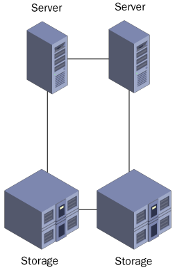
In the context of Windows Server 2003 server clusters, a Fibre Channel
arbitrated loop is a ring topology that connects cluster servers with a
collection of storage devices, as shown in Figure 3.
The total number of devices in an arbitrated loop is limited to 126,
but Windows Server 2003 limits the number of servers in an arbitrated
loop cluster to two.

A Fibre Channel
arbitrated loop is a shared network medium, which is one reason for the
two-server limit. Data packets transmitted by one device on the loop
might have to pass through other devices to reach their destinations,
which lowers the overall bandwidth available to the individual devices.
Compared to switched fabric, arbitrated loop is a relatively inexpensive
clustering hardware technology that enables administrators to easily
expand their storage capacity (although not the number of cluster
nodes).
Fibre Channel Switched Fabric
The only shared storage solution supported by Windows Server 2003 that
is suitable for server clusters of more than two nodes is the Fibre
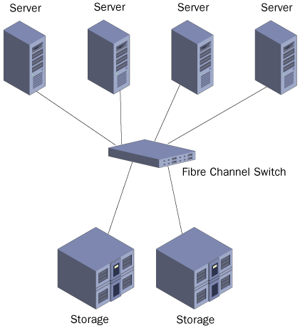
Channel switched fabric network. FC-SW is similar in configuration to a
switched Ethernet network, in which each device is connected to a
switch, as shown in Figure 4.
Switching enables any device on the network to establish a direct,
dedicated connection to any other device. There is no shared network
medium, as in FC-AL; the full bandwidth of the network is available to
all communications.

An
FC-SW network that is wholly dedicated to giving servers access to data
storage devices is a type of SAN. Building a SAN to service your server
cluster provides the greatest possible amount of flexibility and
scalability. You can add nodes to the cluster by installing additional
servers and connecting them to the SAN, or expand the cluster’s shared
storage capacity by installing additional drives or drive arrays. You
can also build a geographically dispersed server cluster by extending
the SAN to locations in other cities.