When studying for the Microsoft 70-642 certification
exam, you spent much of your time understanding how to administer and
maintain a Windows network and the problems and challenges that can
occur when doing so. Now, you'll take a broader look at the technologies
available and develop an overall scheme that you can deploy in your
Windows-based environment. You'll do this by using various addressing
techniques, subnets, scopes, and variable-length subnet masking for host
assignment.
1. Addressing Techniques
For the most part, you have
used three different types of IP addressing techniques: automatic
private IP addressing (APIPA), static, and dynamic (via DHCP).
1.1. APIPA
APIPA addressing
is a Windows default mechanism for assigning IP addresses when a DHCP
server is unreachable. This means that, no matter what the situation,
machines running Windows will always have a logical address available to
them within the 169.254.X.X range. For the most part, other than
trivia, this addressing scheme is used at the MCITP level only as a
reference to machines that are not communicating properly with DHCP.
1.2. Static
Static,
or manual, addressing is the process of manually assigning an IP
address to a machine based on a design created by an individual engineer
or administrator. If network engineers could have their way, chances
are that all IP addresses would be static. Unfortunately, in the modern
day, that simply isn't possible because of the sheer number of addresses
that have to be assigned.
1.3. Dynamic
Dynamic
addressing is a technique that takes advantage of the Dynamic Host
Control Protocol (DHCP) role that can be added to Windows Server. DHCP
then automatically assigns addresses to requesting client machines
through a predetermined pool within your DHCP server defined by the
administrator. At the enterprise level, this is normally the most
heavily used and implemented standard because of the ease, flexibility,
and relatively equal efficiency of its addressing methods.
2. Address Ranges
When designing a
network, the first step is to specifically establish the overarching
breadth of what your design will need to encompass. This can vary wildly
based on budget, number of users, addressing conventions (IPv4 or
IPv6), and expectations of growth. At the top level, you first decide
the addressing scheme you're going to use based on your needs within an
address range.
2.1. IPv4 Address Ranges
Within a few years, the old
method of IP address class ranges will become obsolete. With the advent
of Internet Protocol version 6 (IPv6), the Internet now has simply so
many different addressing assignments available on both the network and
host levels that it's unlikely we'll run out any time in the near
future, but stranger things have happened. Regardless, for the next few
years, Internet Protocol version 4 (IPv4) will remain the most commonly
used addressing assignment system in use.
IPv4 uses a set of four octets
to create an individual, but not necessarily unique, logical address
that can be used for the purposes of routing packets across networks.
This is then further defined by a subnet mask, which partitions the
address into different subnets for the purpose of sending and receiving
broadcast traffic. At the top level, IP addresses are divided into five
different classes that use a certain amounts of bits in the subnet mask
for the network portion of your network and a certain amount of bits for
your various hosts. It's rare that you'll discover a network
administrator who uses all five classes of IPv4 addresses. For the most
part, you are concerned with three different class levels of IP
addresses: Class A, Class B, and Class C, which are described in Table 1.
Each of these addressing classes has its own strengths and weaknesses,
in that each can assign only a certain number of IP addresses based on
the number of available host bits in the subnet mask.
Table 1. IPv4 Address Class Specifications
| Address Class | Number of Network Bits | Number of Available Host Bits | Maximum Hosts |
|---|
| Class A | 8 | 24 | 16,777,214 |
| Class B | 16 | 16 | 65,534 |
| Class C | 24 | 8 | 254 |
Furthermore, each of
these classes of networks is assigned certain ranges that will be
predefined for your network design. Given your address class, you will
fall into one of the ranges of Table 2.
Table 2. IPv4 Address Class Network Range
| Address Class | Network Range |
|---|
| Class A | 1.0.0.0 to 126.255.255.255 |
| Class B | 128.0.0.0 to 191.255.255.255 |
| Class C | 192.0.0.0 to 223.255.255.255 |
When designing an addressing scheme, choosing (or discovering)
your address class is your very first step. You need to determine both
how many networks you require in your infrastructure and, perhaps more
important, how many users are contained within these networks. Once you
have determined this, you can then begin the process of subnetting your
network.
2.2. IPv6 Address Ranges
Unlike its younger brother,
IPv4, IPv6 no longer uses address classes. Instead, IPv6 uses prefixes
that are subdivided by geographic locations around the world. Within
those regions, the addresses are then subdivided more and more until its
gets down to the individual level. In effect, this removes the need for
the old fallback of the IPv4 addressing system, Network Address
Translation (NAT). By design, IPv6 allows for every individual computer
to theoretically have both a unique MAC address and a unique logical IP
address, because so many addresses are available. Unlike IPv4, IPv6 uses
eight quartets, making for a total of 128 bits worth of addressing
space available.
NOTE
This book assumes you have a
strong grasp of manual subnetting, including the ability to convert to
and from binary, hex, and decimal. The examples from this point on
require this and do not review that material. Thus, if you're struggling
to remember all the mathematical techniques involved, it's a good idea
to pick up the MCTS: Windows Server 2008 Network Infrastructure Configuration Study Guide (Sybex, 2008) and review the section on subnetting.
3. Addressing and Subnetting IPv4
3.1. Working with the Number of Hosts and Subnetworks
In the past, Microsoft has
asked lots of general subnetting questions of students just to make sure
they understand the impact of choosing a particular subnet. The way
that this is done is by examining both the host and network portions of
the subnet mask and using a little mathematics to determine the number
of available hosts and subnets that are possible.
For instance, you may be asked
something akin to this: "If you're using a Class C address and you need
to make sure your highly interactive network applications do not
broadcast to more than five computers on the subnet, what would be the
most appropriate mask to use?"
Or, building on the last
example, you might be asked this: "Now that you have determined the
amount of host bits required for your particular subnet, will you be
able to accommodate 30 different subnetworks?"
In the following sections,
you'll explore each of these questions and see whether you can find an
easy way to calculate both of these answers. You'll start with
determining the number of host bits.
3.1.1. Calculating Host Bits and Determining the Subnet Mask
In this scenario, you've been
given a design requirement that no more than six computers exist on the
same network (one application computer + five additional computers).
Remember, the primary goal of a router is to stop broadcast traffic.
And, in order to communicate from one subnet to another, you have to use
a router. Thus, you have to determine the appropriate subnet mask to
accommodate four hosts.
The following is the default subnet mask for a Class C address:
11111111.11111111.11111111.00000000
The part in bold is referred to as the host
portion of the subnet mask. And the eight 0s refer to eight individual
bits. The way you can determine the number of hosts is by taking 2,
raising it to the number of available host bits, and then subtracting 2
again to give room for the broadcast address and the network address. In
this case, the amount of available hosts would be 28 − 2 = 254.
So, with that in mind,
let's look at the example where you need four hosts per subnet. The
easiest way to do this is by seeing which power of 2 gives you at least
two more addresses than you need and then use that. You do this to
accommodate for the broadcast and network addresses. Here are the powers
of 2:
21 = 2
22 = 4
23 = 8
24 = 16
25 = 32
26 = 64
27 = 128
28 = 256
As you can see, in order to
accommodate at least two more than 4 (in this case four more), you need
to use 2⁁3 bits. In total, this gives you 23 – 2 = 6 hosts.
So if you need three host
bits to get six hosts, your network portion can take up all but 3 bits!
That means the subnet mask for this problem is as follows:
11111111.11111111.11111111.11111000
The network portion is as follows:
11111111.11111111.11111111.11111000
And the host portion is as follows:
11111111.11111111.11111111.11111000
In shorthand, you would
write this mask as /29, because it uses 29 bits. But the actual value
for this mask is 255.255.255.X, where X is the last octet in decimal.
And the number 11111 in decimal happens to be 248. Thus, the mask for
this problem is as follows:
255.255.255.248
3.1.2. Determining the Number of Subnetworks
The next portion of the
problem asks you to determine whether you can accommodate 30 different
subnetworks. This can be easily answered by examining the number of subnet bits available to you. Since you're using a Class C address, you look at the network portion of the last octet only:
11111111.11111111.11111111.11111000
This is referred to as the subnet bits
portion of the network portion of the subnet mask (that's a lot to say
at once). But in reality, it's pretty easy to understand. This size
grows and shrinks based on two factors. First, there is the address
class. If you were using a Class A address, you'd look at all the
networks bits in the second, third, and fourth octet combined. And if
you were using a Class B address, you'd look at the third and fourth
combined.
But since you're looking at a
Class C address, you can just count those last five subnet bits. That
is, you look at the 11111 portion of the 11111000 octet. And then, since
you know it takes 5 bits, you can just raise 2 to the number of host
bits (5) and derive the answer: 25 = 32.
Thus, you have 32 subnetworks available, so, yes, you can accommodate the design requirements!
3.2. Addressing a Given Topology
The most common way you might
be required to subnet on the MCITP exam is by being given a standard
topology and then being asked to subnet the topology using only public
addresses. The purpose of this exercise is to prove that you both
understand how to subnet and can effectively design a complex
infrastructure using Windows Server 2008. Normally, you will be given a
diagram like Figure 1.
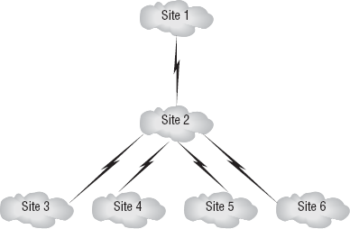
In the network diagram in Figure 2.1,
your topology requires six different subnetworks because your overall
design contains six different sites. Of course, from a Windows
administrator point of view, this means you're going to have a lot of
work on your hands: you have to subnet the network; connect the
different subnets with site links; verify your replication strategy,
schedule, and connections; and then do a little quality assurance to
make sure everything is functioning properly. For now, you will stick to
the initial process of subnetting the network. Let's assume for the
moment that you have been given the Class C IP address range of
209.81.3.0.
Remember, this address is Class
C because the first octet is greater than 192. This also means there is
only a single address, but you require six different subnetworks
because of the earlier requirements. To support this many networks, you
have to do a minor calculation with a portion of your subnet mask, the
last octet. Normally, the default subnet mask for a Class C network is
as follows:
111111111.11111111.11111111.00000000
Or, written in decimal
format, it's simply 255.255.255.0. Now, because you're operating within
the boundaries of a Class C address, you're concentrating only on the
last octet: 00000000.
The first objective, as you
might imagine, is to make sure you have enough space in your subnet mask
to support the amount of networks you need to accomplish your
objective. To do this, you simply take the number of networks you need
(six in this case) and go up the binary digits of binary notation until
you reach a number greater than your original number:
| First digit | 20 = 1 (not enough networks) |
| Second digit | 21 = 2 (not enough networks) |
| Third digit | 22 = 4 (not enough networks) |
| Fourth digit | 23 = 8 (two more networks than required) |
|
Whenever you're designing your
network, keep in mind that you'll always want to have room to grow. In
this case, you have room for two more networks. Thus, if you add more
sites, you will be able to accommodate a few more networks without
having to reorganize your entire structure.
|
|
So, you had to travel down four digits in binary in order to reach a
number greater than six, your required amount of networks. Now, because
you have this number, you can allocate the network portion of your
subnet mask! Remember, the first bits of the subnet mask are the network portion, and the second bits are the host portion. So, instead of your default mask, shown in Figure 2, you move 4 bits in to subdivide your network, as shown in Figure 3.


And thus, you now have a subnet mask for the entire network! Pretty cool, huh? However, this isn't the end of the process.
Whenever you subdivide a
network into different portions, you have to understand what the range
of your IP addresses is. This is because, naturally, a subnetted network
cannot communicate with an IP address that is out of the range of its
own subnet without a router. Finding these address ranges is actually a
pretty simple process. You just take the last number of your subnet mask
and see what it corresponds to in decimal notation.
In this case, you take the value shown here:
11111111.11111111.11111111.11110000
This value of 1 in the fourth
spot in the mask is actually 32 in decimal notation. What this number
means to you is that by starting at zero in the octet of concern
(the first octet for Class A, the second octet for Class B, and the
third octet for Class C), you add by 32 until you reach the number 256,
which is outside the scope of a single octet of numbers. This will give
you the network addresses (or network IDs) for the available
subnetworks.
This is a lot easier to
understand if you see it. All it means is that you can take your
starting address and find your network identifiers by starting at 0 and
adding 32 like this:
209.81.3.0
209.81.3.32 (0 +32)
209.81.3.64 (32 + 32)
209.81.3.96 (64 + 32)
209.81.3.128 (96 + 32)
209.81.3.160 (128 + 32)
209.81.3.192 (160 + 32)
209.81.3.224 (192 + 32)
Then, after you have
your network identifier, you can find the broadcast address (the
address that allows information to be sent to all devices within the
subnet) by subtracting 1 from the last octet in all these numbers, with
the exception of 0:
209.81.3.31 (32 – 1)
209.81.3.63 (64 – 1)
209.81.3.95 (96 – 1)
209.81.3.127 (128 – 1)
209.81.3.159 (160 – 1)
209.81.3.191 (192 – 1)
209.81.3.223 (224 – 1)
209.81.3.254 (256 – 1)
Then, you can find your usable addresses by looking at all the addresses between! You can see this illustrated in Table 3.
Table 3. Defining Network Address Ranges
| Network Address | Broadcast Address | Usable Addresses |
|---|
| 209.81.3.0 | 209.81.3.31 | 209.81.3.1–30 |
| 209.81.3.32 | 209.81.3.63 | 209.81.3.33–62 |
| 209.81.3.64 | 209.81.3.95 | 209.81.3.65–94 |
| 209.81.3.96 | 209.81.3.127 | 209.81.3.97–126 |
| 209.81.3.128 | 209.81.3.159 | 209.81.3.129–158 |
| 209.81.3.160 | 209.81.3.191 | 209.81.3.161–190 |
| 209.81.3.192 | 209.81.3.223 | 209.81.3.193–222 |
| 209.81.3.224 | 209.81.3.254 | 209.81.3.225–253 |
Most network administrators will steer you away from using the first and last subnet ranges, called the subnet zero and all-ones
subnets. The reason behind this is that in the all-ones subnet, there
can be confusion because you have a subnet with an identical broadcast
address. Using the subnet-zero subnet was discouraged because you could
have a subnet that was just 0. So, imagine seeing an IP address like
172.16.1.11 and having it be in the 172.16.0.0 subnet. Therefore, in
practice, most administrators will say there are 2N-2 usable subnets.
However, the strategy I have
just discussed is an exceptionally powerful tool, and truth be told, you
will be able to use this technique on more than just your MCITP
certification exam. Many, many certifications use this technique, and if
you've already mastered it, you're well on your way to attaining even
more impressive titles.
Now, take a look back at Figure 2.1
again. Now that you have your network IDs, broadcast IDs, and usable
addresses, you can assign each of these sites to a subnetwork and then
start assigning them accordingly. If you'd like to see this in action,
check out the "Readdressing a Network" sidebar.
|
You have just recently
become employed with MegaCorp, a multibillion-dollar corporation that
has placed you in charge of approximately 100 users within its
organization. Currently, your portion of the organization is broken down
into three separate networks connected by WAN connections. Today, the
head office has decided it wants to readdress your network with the
given address space of 209.113.60.0/27.
Specifically, MegaCorp wants
to make sure the fewest number of possible subnetworks is used but that
each of these sustains enough host bits to support the required number
of users. Given the network topology shown here, what subnet mask would
you need to apply for the entire network, and what three separate
broadcast addresses would you need to assign, assuming that the
corporate specifications for network design require the lowest
incremental broadcast address to be applied to Site A, then the next
highest to Site B, and so forth? Growth is not a consideration in this
design.
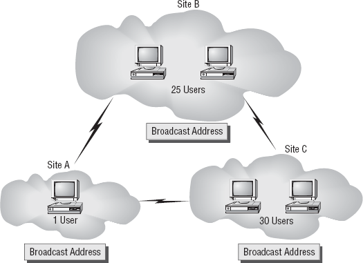
Answer: Since you have no
network with more than 30 users, you know you will need to reserve only
enough host bits to maintain 30 users. Additionally, you have been told
that growth is not an issue.
The number 30 in binary is 00011110.
Thus, when you look at this
number, you realize that you require 5 bits for your host portion and 3
bits for your network portion. Thus, your default mask assigned by the
head office of /27 will be appropriate. This is because the default mask
of /24 for Class C, plus the additional 3 bits for your specific
requirements, creates a need for a /27 subnet mask. However, to complete
the design, you must define your broadcast addresses. These are
discovered by taking the incremental number of the network, which is
found by taking the binary value of the last bit in the network portion,
incrementing the IP address by that value, and then subtracting zero.
In your case, your mask is as follows:
11111111.11111111.11100000
And the binary value of the 1 at
the 27th spot is 32. Thus, your incremental value is 32, giving you
this as your network addresses:
209.113.60.0 209.113.60.32 209.113.60.64 209.113.60.96
This allows you to subtract 1 from 32, 64, and 96 for your broadcast address:
Site A broadcast = 209.113.60.31 Site B broadcast = 209.113.60.63 Site C broadcast = 209.113.60.95
|
3.3. VLSM
Variable-length
subnet mask (VLSM) is a technology concept that is used throughout
networks that have great subnetting requirements but require the least
amount of waste and most efficient use of broadcast traffic possible.
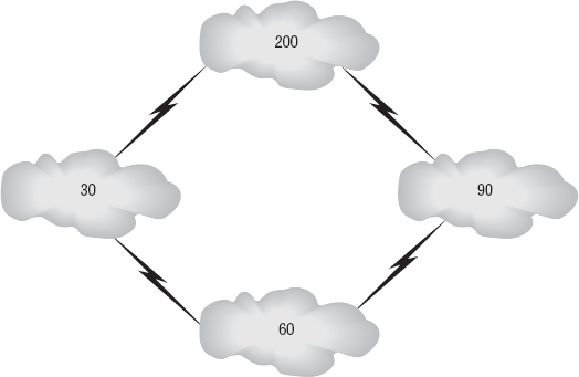
Imagine for a moment that you work for MyCorp again and that you have a
user situation in your office that breaks down as shown in Figure 4.
As you can see, the network is
broken up into four individual subnets, and each of those subnets has a
different user requirement. In the first subnet, you require 200 users,
in the second you require 30, and so forth. Normally, you would break
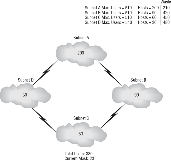
this network up by subnetting it into four individual groups, Subnet A,
B, C, and D. But let's look at what happens if you do that; see Figure 5.
On the right side of the figure,
you'll see the maximum number of hosts that can be contained on the
subnet. To the right of this, you'll see your actual number of users,
and then on the far right you can see the amount of wasted addresses
within this space. Now, as you can imagine, especially with high-end
networking, space matters.
Part of being an
enterprise administrator is understanding that your ultimate goal for
your enterprise is to make sure that everything is running as often as
possible and as efficiently as possible. In your career up until this
point, someone has undoubtedly told you that the best way to become
successful in life is not to waste anything. This includes money,
opportunities, and, of course, host addresses. Instead, consider what
would happen if you could apply an individual subnet address for each of
these subnetworks. For instance, using some basic calculations that you
learned earlier, you could determine that the following masks could be
used based on the host requirements:
| Subnetwork A: | Requires 200 hosts | 8 bits | 255.255.255.0 subnet mask |
| Subnetwork B: | Requires 90 hosts | 7 bits | 255.255.255.128 subnet mask |
| Subnetwork C: | Requires 60 hosts | 6 bits | 255.255.255.192 subnet mask |
| Subnetwork D: | Requires 30 hosts | 5 bits | 255.255.255.224 subnet mask |
This sure would be nice if you
could do it, wouldn't it? The truth is, you can. VLSM allows
administrators to apply a more specific subnet mask to a preexisting
subnet mask to further define a subnet. This is extraordinarily useful
for complex organizations and can really optimize your efficiency.
Consider your first example, where the same mask was applied throughout,
and consider your latest example, shown in Figure 6, which uses VLSM.
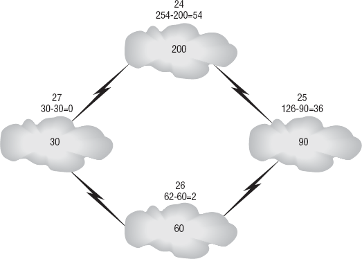
The numbers speak for themselves.
Now, if you wanted to apply
these addresses to your network, you'd have to go one step further and
calculate the address ranges where you would need to apply them. First
you'd start by taking 2 and raising it to the required number of bits
per individual subnet mask to find out an incremental number like you
did earlier. Now, you've managed to subnet your network into several
different areas and saved yourself tons of IP addresses!