Creating a Failover Cluster
When the failover cluster is
first created, all nodes in the cluster should be up and running. The
exception to that rule is when failover clusters utilize direct attached
storage such as Serial Attached SCSI devices that require a process of
creating the cluster on a single node and adding other nodes one at a
time. For clusters that will not use shared storage or clusters that
will connect to shared storage using iSCSI or Fibre Channel connections,
all nodes should be powered on during cluster creation. To create the
failover cluster, perform the following steps:
1. | Log
on to one of the Windows Server 2008 R2 cluster nodes with an account
with administrator privileges over all nodes in the cluster.
| 2. | Click Start, click All Programs, click Administrative Tools, and select Failover Cluster Manager.
| 3. | When
the Failover Cluster Manager console opens, click the Create a Cluster
link in the Actions pane under the Management heading.
| 4. | When the Create Cluster Wizard opens, click Next on the Before You Begin page.
| 5. | On
the Select Servers page, enter the name of each cluster node, and click
the Add button. When all the nodes are listed, click Next to continue.
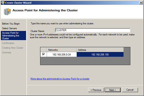
| 6. | On
the Access Point for Administering the Cluster page, type in the name
of the cluster, complete the IPv4 address, and click Next, as shown in Figure 3.
| 7. | On the Confirmation page, review the settings, and click Next to create the cluster.
| 8. | On
the Summary page, review the results of the cluster creation process,
and click Finish to return to the Failover Cluster Manager console. If
there are any errors, you can click the View Report button to reveal the
detailed cluster creation report.
| 9. | Back
in the Failover Cluster Manager console, select the cluster name in the
tree pane, if not already selected by default, and in the tasks pane,
review the configuration of the cluster.
| 10. | In the tree pane, select and expand the cluster to reveal the Nodes group to list all of the cluster nodes.
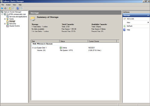
| 11. | Select Storage and review the cluster storage in the tasks pane listed under Storage, as shown in Figure 4.
| 12. | Expand
Networks in the tree pane to review the list of networks. Select each
network and review the names of the adapters in each network.
| 13. | When
reviewing is completed, the initial cluster deployment is complete.
Close the Failover Cluster Manager console and log off of the cluster
node.
|
After the cluster is
created, additional tasks should be performed before any Services and
Applications groups are created using the High Availability Wizard.
These tasks can include, but might not require, customizing the cluster
networks, adding storage to the cluster, adding nodes to the cluster,
and changing the cluster quorum model.
Configuring Cluster Networks
After the cluster is created,
several steps should be taken to improve cluster management. One of
these tasks includes customizing the cluster networks. Each node in the
cluster should have the same number of network adapters and each adapter
should have already been renamed to describe a network or to easily
identify which network a particular network adapter belongs to. After
the nodes are added to the failover cluster, for each network card in a
cluster node, there will be a corresponding cluster network. Each
cluster network will be named “Cluster Network 1,” “Cluster Network 2,”
and so forth for each network. Each network can be renamed and can also
be configured for use by the cluster and clients, for internal cluster
use only, or the network can be excluded from any cluster use. Networks
and network adapters used for iSCSI communication must be excluded from
cluster usage. Now excluding iSCSI networks from cluster usage might
seem strange, especially if iSCSI disks are used for the cluster, but
this is intended to ensure that only iSCSI communication is passed to
that network and no unnecessary cluster communication is competing for
NIC resources when disk access might be critical. To customize the
cluster networks, perform the following steps:
1. | Log
on to one of the Windows Server 2008 R2 cluster nodes with an account
with administrator privileges over all nodes in the cluster.
| 2. | Click Start, click All Programs, click Administrative Tools, and select Failover Cluster Manager.
| 3. | When
the Failover Cluster Manager console opens, if necessary type in the
name of the local cluster node to connect to the cluster.
| 4. | When the Failover Cluster Manager console connects to the cluster, select and expand the cluster name.
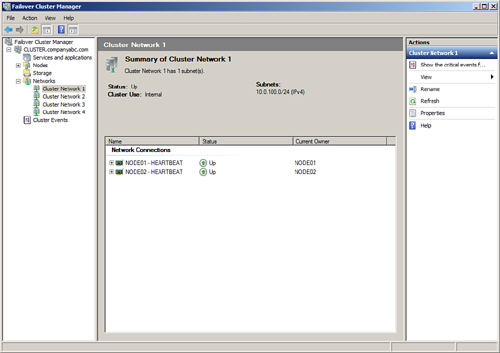
| 5. | Select and expand Networks in the tree pane, and select Cluster Network 1 as an example.
| 6. | In the tasks pane, review the name of the network adapters in the network, as shown in Figure 5, for the HEARTBEAT network adapters that are members of Cluster Network 1.
| 7. | Right-click Cluster Network 1, and select Rename. Rename the cluster to match the network adapter name.
| 8. | For this example, right-click the renamed HEARTBEAT network, and select Properties.
| 9. | Select
the Allow Cluster Communication on This Network option button, and do
not check the check box to allow clients to connect through this
network. Click OK when completed.
| 10. | Back
in the Failover Cluster Manager console, rename the remaining cluster
networks and verify that each network is configured for the proper
cluster only or cluster and client communication. iSCSI network
interface cards should be configured to not allow cluster network
communication and production networks should be configured to allow
cluster network communication and to allow clients to connect through
the network.
| 11. | When
all of the networking changes are complete, click on the Networks node
in the tree pane and the networks should be listed similarly to Figure 6. Close the Failover Cluster Manager console and log off of the server.

|
|
