Triangle Normals
For more realism, take
into account the direction the triangle faces in regards to the light.
To help determine the direction a triangle is facing, use the normal of
the triangle. The normal contains only a direction and, therefore,
should always have a length of 1. It is important that you normalize or
set the length to 1 of a normal anytime you perform a calculation that
alters the normal’s size.
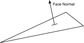
There are two types of normals
when working with a triangle. The first is called a face normal and is
defined to be perpendicular to the plane that is defined by the three
points that make up the triangle. Figure 2 shows an example of a face normal.
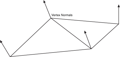
In real-time 3D graphics, the
second type of normal called a vertex normal is used. Each vertex of the
triangle defines its own normal. This is useful because you might want
the object to appear smooth. In this case, the normal at a vertex is
averaged with values from adjacent triangles to enable a smooth
transition from one to the other. Figure 3 shows an example of vertex normals.
You can update the
previous example to display the normal values of the mesh with just a
few code changes. No changes need to be made on the game code side, and
you need to make only a couple of changes to the shader.
Update the input and output vertex structures to the following:
struct VertexShaderInput
{
    float4 Position : POSITION0;
    float3 Normal   : NORMAL;
};
struct VertexShaderOutput
{
    float4 Position : POSITION0;
    float3 Normal   : TEXCOORD0;
};
The
Normal value is added to each structure. The NORMAL semantic used in
the input structure tells the graphics card that you want the normal
data from the model. It is matched to the corresponding data from the VertexBuffer where the VertexDeceleration has set the normal channel.
Note
The model used in this
example contains normal data. This exports from the modeling package
used to create the model. If your model does not contain normal data,
then you see an exception when you try to draw the model.
In the vertex shader, pass
the normal data from the input structure to the output structure. Add
the following line of code before you return the output structure:
output.Normal = input.Normal;
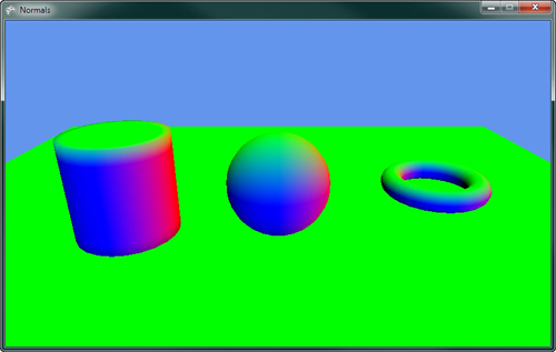
The normal data
interpolates between each vertex across the triangle for each pixel. In
the pixel shader, read this normal value and use the components of the
vector as the red, green, and blue color.
Update the pixel shader with the following line of code that returns the normal data as a color:
return float4(normalize(input.Normal), 1);
The normal needs to be
normalized because the interpolation can lead to normals with length not
equal to 1. The three components of the normal are then combined with
an alpha value of 1 to color the pixel. If you run the example, it
displays a rainbow of colors similar to Figure 4.
Diffuse Lighting
The term diffuse means
to scatter or become scattered, so the diffuse light is reflected light
that bounces off in many directions causing an object to appear to be
flat shaded and not shinny. Ambient lighting, which gives a constant
color across the triangles in a mesh diffuse lighting, differs depending
on the angle of the triangle to the light source. Use Lambert’s cosine
law, which is a common equation used to determine the diffuse color.
This law states that the light reflected is proportional to the cosine
of the angle between the normal and the light direction.
The type of lighting you are
going to model first is called directional light. The light is
considered to come from a constant direction in parallel beams of light.
This is similar to how sunlight reaches earth.
Note
Sunlight
is not parallel but for 3D graphics purposes, it can be treated that
way because the size and distance of the sun is so great that the light
appears to reach earth as parallel beams.
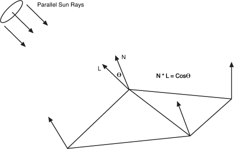
Because Lambert says you can
use the cosine of the angle between the normal and the light, you can
easily calculate this by taking the dot product of the normal and the
light direction vectors. If both are unit length, then the dot product
is equal to the cosine of the angle, which is the value you want.
Figure 5 shows the directional lights parallel rays hitting the triangle normals and the angle calculation.
Let’s add some diffuse lighting
from a directional light to the previous example of ambient lighting.
The first thing you need are some additional member variables in your
game class.
// The direction the light comes from
Vector3 lightDirection;
// The color and intensity of the diffuse light
Vector3 diffuseLightColor;
The first variable lightDirection
is exactly what the name describes—the direction the light is going in.
There are two ways to describe the direction of a directional light.
The first is to describe the direction the light is moving in. This is
the way we describe the light in the example. The second is to describe
the direction to the source of the light like pointing towards the sun.
This is the way you need the value in your shader so you can perform the
angle calculation using the dot product.
The second variable is the color
of the light. Lights don’t always have to be white; they can be
different colors. Each color channel affects the same color channel of
the object’s diffuse color.
In your game’s Initialize
method, add the following lines of code to set the light’s direction
and color. Note that the direction is normalized to keep the vector at
unit length.
// Set light starting location
lightDirection = new Vector3(-0.5f, -0.5f, -0.6f);
lightDirection.Normalize();

// Set the lights diffuse color
diffuseLightColor = new Vector3(1, 0.9f, 0.8f);
The final changes you need to make to your game code is to send the values to the Effect. Set the LightDirection and DiffuseLightColor
just after the other effect wide parameters as the following code
shows. The light direction is negated to change it from pointing from
the light to be the direction to the light. This is the format you need
in your shader, so make it here instead of calculating the negation
multiple times in the shader.
// Set effect wide parameters
diffuseEffect.Parameters["View"].SetValue(view);
diffuseEffect.Parameters["Projection"].SetValue(projection);
diffuseEffect.Parameters["AmbientLightColor"].SetValue(ambientLightColor);
diffuseEffect.Parameters["LightDirection"].SetValue(-lightDirection);
diffuseEffect.Parameters["DiffuseLightColor"].SetValue(diffuseLightColor);
Now, update your custom effect file to calculate the diffuse color in addition to the ambient color.
The first change is to add two new global variables that are used to store the light direction and color.
float3 LightDirection;
float3 DiffuseLightColor;
Like the normal example, add the vertex normal to both the input and output vertex structures.
struct VertexShaderInput
{
    float4 Position : POSITION0;
    float3 Normal   : NORMAL;
};

struct VertexShaderOutput
{
    float4 Position : POSITION0;
    float3 Normal   : TEXCOORD0;
};
The normal values also need to be passed from the input to the output structure in the vertex shader.
output.Normal = mul(input.Normal, World);
Finally, update the pixel
shader to calculate the diffuse color and output the color for the
pixel. Update the pixel shader with the following code:
float4 PixelShaderFunction(VertexShaderOutput input) : COLOR0
{
    // Normalize the interpolated normal
    float3 normal = normalize(input.Normal);

    // Store the final color of the pixel
    float3 finalColor = float3(0, 0, 0);

    // Start with ambient light color
    float3 diffuse = AmbientLightColor;

    // Calculate diffuse lighting
    float NdotL = saturate(dot(normal, LightDirection));
    diffuse += NdotL * DiffuseLightColor;

    // Add in diffuse color value
    finalColor +=  DiffuseColor * diffuse;

    return float4(finalColor, 1);
}
First,
the pixel shader normalizes the input normal. You need to normalize
this value because the interpolation between vertices can lead to the
vector not having a unit length. Then, set the minimum value for the
diffuse lighting to the ambient light value. This is the minimum that
the pixel can be lit. The additional light from the directional light is
added to this value.
To calculate the
light from the directional light, calculate the value of the dot product
of the normal and the light direction. Use the saturate
intrinsic function to clamp the value between 0 and 1. If the dot
product is negative, then it means the normal is facing away from the
light and should not be shaded so you want a value of 0 and not the
negative value of the dot product.
The NdotL value is then
multiplied by the color of the directional light and added to the
diffuse light amount. The diffuse light amount is then multiplied by the
diffuse color of the object itself to obtain the final color of the
object. The final color is then returned with an alpha value of 1.
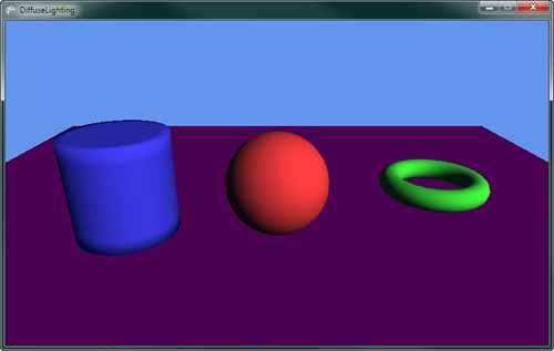
If you run the previous code sample, you should see something similar to Figure 6.
Multiple Lights
In the real world, you have
more than one light source. You can also have more than one directional
light. To add an additional light, add an additional light direction and
color to your game class.
// The direction and color of a 2nd light
Vector3 lightDirection2;
Vector3 diffuseLightColor2;
Next, give them some default values in the game’s Initialize method.
// Set the 2nd lights direction and color
lightDirection2 = new Vector3(0.45f, -0.8f, 0.45f);
lightDirection2.Normalize();
diffuseLightColor2 = new Vector3(0.4f, 0.35f, 0.4f);
Then, send the values to the Effect.
diffuseEffect.Parameters["LightDirection2"].SetValue(-lightDirection2);
diffuseEffect.Parameters["DiffuseLightColor2"].SetValue(diffuseLightColor2);
In the shader effect file, add the following two new global variables:
float3 LightDirection2;
float3 DiffuseLightColor2;
In the pixel shader,
calculate the dot product of the additional light and add the value to
your diffuse light value before adding the value to the finalColor.
// Calculate 2nd diffuse light
NdotL = saturate(dot(normal, LightDirection2));
diffuse += NdotL * DiffuseLightColor2;
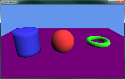
Running the example now should show something similar to Figure 7.
Oversaturation
As you add more
lighting, the possibility of oversaturation becomes a concern. Notice
that lighting is additive. As you add more lights, the final color
channel values can go above 1, which
is full color. As the values go above 1, no change in the final pixel
color output the screen occurs. Differences of colors above 1 appear to
be the same color to the user. Portions of an object might lose their
definition becoming bright white or another solid color. You can limit
oversaturation by lowering the amount of lights and keeping the color
intensity values of the lights lower. Notice that the previous example
used smaller values for the second light’s color. Often, you have one
stronger light with an additional couple of weaker lights.
